I'm in the process of repairing a 500S, circa 2002, pcb# PC-3082-D (I have the schematics). The initial problem was a blown output FET on the left channel, sending negative rail voltage to the output terminal. I replaced all 6 FETs on the left channel and reset the bias. That channel works well now, with the output going to within 1-2v of rail before clipping with a 4 ohm load.
While testing the other (right) channel, I found another issue. I either missed this during initial diagnosis, or something got damaged during the repair. The output, with or without a load, clips well before reaching rail voltage. The clipping is equal on both the positive and negative side of the signal. Another symptom is that it appears the overall gain of the right channel is less than that of the left channel (for equal input signals). It's almost as if that channel has no gain, and the signal at the output terminal is merely the input signal fed via the feedback resistor (R244).
Tracing the signal through the design, and comparing the bad (right) channel to the good (left), I find the following differences:
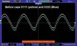
- good signal at the + side of C223 (matches the signal at C111)
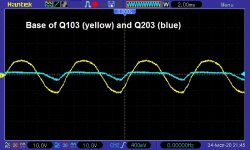
- bad signal at the base of Q203
- bad signal at the collector of Q201
I used my multimeter's diode test function to test Q201, Q202, and Q203. All appeared fine. I also tested all of the resistors in that part of the circuit, and again all was fine. All of the output FETs test fine too. The +/-14v supplies are also good on the right channel (as tested at R215 and R219).
My initial thought was that Q201 wasn't turning on properly, so I tried shorting the collector to emitter. That didn't help, and made the output look worse.
Aside from starting to randomly replace components, where else should I look?
Thanks!
While testing the other (right) channel, I found another issue. I either missed this during initial diagnosis, or something got damaged during the repair. The output, with or without a load, clips well before reaching rail voltage. The clipping is equal on both the positive and negative side of the signal. Another symptom is that it appears the overall gain of the right channel is less than that of the left channel (for equal input signals). It's almost as if that channel has no gain, and the signal at the output terminal is merely the input signal fed via the feedback resistor (R244).
Tracing the signal through the design, and comparing the bad (right) channel to the good (left), I find the following differences:
- good signal at the + side of C223 (matches the signal at C111)
- bad signal at the base of Q203
- bad signal at the collector of Q201
I used my multimeter's diode test function to test Q201, Q202, and Q203. All appeared fine. I also tested all of the resistors in that part of the circuit, and again all was fine. All of the output FETs test fine too. The +/-14v supplies are also good on the right channel (as tested at R215 and R219).
My initial thought was that Q201 wasn't turning on properly, so I tried shorting the collector to emitter. That didn't help, and made the output look worse.
Aside from starting to randomly replace components, where else should I look?
Thanks!
Last edited:
Are you saying that the signal is clipped on both sides of C223?
At what amplitude positive and negative, does it clip?
At what amplitude positive and negative, does it clip?
Are you saying that the signal is clipped on both sides of C223?
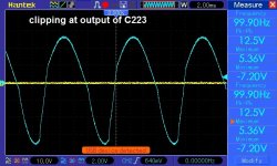
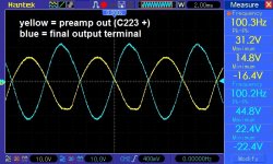
Well yes, but I expect it to clip on the input of C223 eventually (if the gain is too high). On the output of C223, it clips early, at +5v and -7v, and the signal does not look good (see image attached).
At what amplitude positive and negative, does it clip?
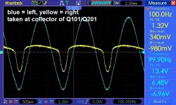
About +/-28v (see attached image). The rails are at +/-40v in this case.
I've attached a bunch of scope captures at the caps and transistor base.
Attachments


You have to understand that we're working 100% blind except for the information that you provide. We can't know what you expect to see. I needed to know if the clipping of the low-gain channel exactly mirrored the preamp signal.
The gain of the right channel depends on the components from the op-amps before the mode switch to the resistor R264 and also R244.
If the problem is precisely the same in all modes, the op-amps are likely OK. The switch, the caps or resistors would be suspect. It could also be a problem in the differential amp.
Are the voltages across the 33 ohm resistors the same in both differential amplifiers?
You have to understand that we're working 100% blind except for the information that you provide. We can't know what you expect to see.
I totally understand.
I needed to know if the clipping of the low-gain channel exactly mirrored the preamp signal.
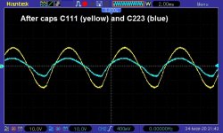
They're very similar (see attached pic). When the preamp signal clips, the output clips (no earlier). The final output is about 1.43x the preamp signal.
The gain of the right channel depends on the components from the op-amps before the mode switch to the resistor R264 and also R244.
If the problem is precisely the same in all modes, the op-amps are likely OK. The switch, the caps or resistors would be suspect. It could also be a problem in the differential amp.
I hadn't considered that. I was doing all of the testing with the switch in All-Pass mode. I checked with the other modes (LP and HP), and the problem remains.
Are the voltages across the 33 ohm resistors the same in both differential amplifiers?
Will check and report back.
Attachments
Are the voltages across the 33 ohm resistors the same in both differential amplifiers?
In the bad channel, the voltage across all points of the 33 ohm resistors are the same (yellow wave in the attached image).
In other words, the emitters of Q202 and Q203, and the collector of Q201, have the yellow wave in the attached screenshot. The blue waveform is the equivalent signal in the good channel.
Does this point to Q201 being bad? (not allowing enough current through the differential amplifier?)
Attachments
Is there absolutely no signal on both terminals of C211?
Does the bias pot for the bad channel work?
If you lift D202 and D204, does that make a difference in the output?
Does the bias pot for the bad channel work?
If you lift D202 and D204, does that make a difference in the output?
Is there absolutely no signal on both terminals of C211?
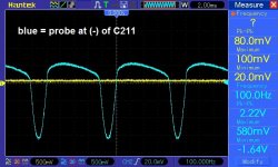
The signal on both terminals of C211 matches that of the signal on the emitters of Q202 and Q203 (picture attached).
Does the bias pot for the bad channel work?
Yes. I've adjusted it to 50ma of draw. If I continue turning it higher, I can trip my 5A power supply.
If you lift D202 and D204, does that make a difference in the output?
I have not tried lifting those yet to see if the protection circuit is the culprit.
Attachments
You have a problem with the scope ground because one terminal of that capacitor is ground. The scope should see noting on that point.
Bear in mind that when things are right, you should see no signals on either of the base terminals of the 200 series channel. The 100 series channel is non-inverting. The 200 series channel is inverting. Like on an op-amp, if the input is to the inverting input and the non-inverting input is grounded, there will be no signal seen on either input.
Bear in mind that when things are right, you should see no signals on either of the base terminals of the 200 series channel. The 100 series channel is non-inverting. The 200 series channel is inverting. Like on an op-amp, if the input is to the inverting input and the non-inverting input is grounded, there will be no signal seen on either input.
You have a problem with the scope ground because one terminal of that capacitor is ground. The scope should see noting on that point.
It was because I had the scope's ground clip connected to the output's ground (ie, HV power supply ground), not the signal ground. Connecting to the signal ground produced a zero signal on the (+) side of C211, but still had a 'bad' signal on the (-) of C211.
Bear in mind that when things are right, you should see no signals on either of the base terminals of the 200 series channel. The 100 series channel is non-inverting. The 200 series channel is inverting. Like on an op-amp, if the input is to the inverting input and the non-inverting input is grounded, there will be no signal seen on either input.
I lifted the protection circuit diodes and the problem remains.
I don't think you should see anything on either terminal of C211. Try paralleling another cap of the same value across it to see if it makes a difference.
I believe I've found the problem. After much troubleshooting of the signal feeding the differential amp circuit, it seems that C223 is faulty. Bypassing that cap results in the right channel outputting the same gain/level as the left channel (and same clip point).
Thanks for all the help!
Thanks for all the help!
- Home
- General Interest
- Car Audio
- Help diagnosing Rockford Fosgate 500S early clipping