hi!
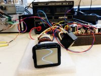
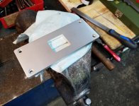
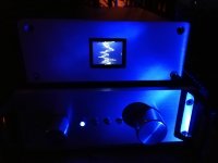
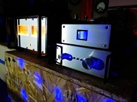
Here is my audioscope project - just because I like uncommon methods to visualize sound
Some time ago, I used a similar circuit as an optical gimmick in an EL84 SE tube amplifier. (With a smaller and round crt YouTube ).
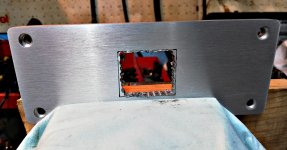
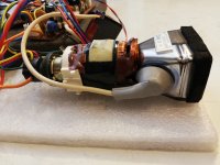
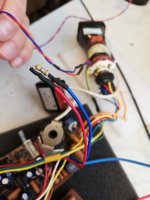
It consists of the electronics out of a 1,77" viewfinder from an early 1980s video camera. I don´t remeber the camera brand and type where it´s teared down from, but it should be easy to find something similar for little money in the Bay.
Newer camera types usually are downsized and contain less impressive CRTs.
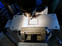
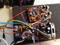
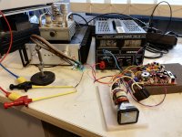
After reverse engineering the viewfinder, put it into operation carefully with the right connections and voltages. Just a small mistake in your considerations, and it burns... I speak from experience 😀
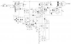
The horizontal deflection coil is disconnected from the circuit, the vertical stays untouched. I´ve integrated a terminating resistor in place of the x-deflection coil, to keep the circuit running.
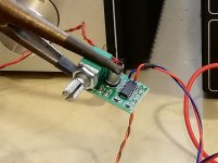
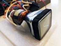
With a small audio amplifier module like PAM8403, it´s able to modulate the CRT deflection.
This procedure is easily reproducible and not critical, if you manage to analyse the viewfinder electronics right 🙄
-> video: YouTube
Here is my audioscope project - just because I like uncommon methods to visualize sound
Some time ago, I used a similar circuit as an optical gimmick in an EL84 SE tube amplifier. (With a smaller and round crt YouTube ).
It consists of the electronics out of a 1,77" viewfinder from an early 1980s video camera. I don´t remeber the camera brand and type where it´s teared down from, but it should be easy to find something similar for little money in the Bay.
Newer camera types usually are downsized and contain less impressive CRTs.
After reverse engineering the viewfinder, put it into operation carefully with the right connections and voltages. Just a small mistake in your considerations, and it burns... I speak from experience 😀
The horizontal deflection coil is disconnected from the circuit, the vertical stays untouched. I´ve integrated a terminating resistor in place of the x-deflection coil, to keep the circuit running.
With a small audio amplifier module like PAM8403, it´s able to modulate the CRT deflection.
This procedure is easily reproducible and not critical, if you manage to analyse the viewfinder electronics right 🙄
-> video: YouTube
Attachments
-
 Audioscope-Aufbau-21a.jpg618.7 KB · Views: 286
 -
 Audioscope-Aufbau-10a.jpg507.9 KB · Views: 141
 -
 Audioscope-Aufbau-5a.jpg619.1 KB · Views: 128
 -
 Audioscope-Aufbau-11a.jpg216.4 KB · Views: 125
 -
 Audioscope-Aufbau-12b.jpg618.2 KB · Views: 123
 -
 Audioscope-Aufbau-9a.jpg657.5 KB · Views: 127
 -
 Audioscope-Aufbau-6a.jpg459.4 KB · Views: 262
 -
 Audioscope-Aufbau-4a.jpg869.5 KB · Views: 282
 -
 aAudioscope-Aufbau-21a.jpg494.2 KB · Views: 265
 -
 Audioscope-Aufbau-1a.jpg850.3 KB · Views: 308
Last edited:


Interesting project, cool, there was a series of Marantz receivers with a round CRT and displaying switchable parameters.The horizontal deflection coil is disconnected from the circuit, the vertical stays untouched. I´ve integrated a terminating resistor in place of the x-deflection coil, to keep the circuit running.
With a small audio amplifier module like PAM8403, it´s able to modulate the CRT deflection.
So how do you get horizontal deflection if the H coil is disconnected ?.
Max.
A.C signal from the small audio amplifier output used as horizondal driver signal (connected to horizontal coil).Interesting project, cool, there was a series of Marantz receivers with a round CRT and displaying switchable parameters.
So how do you get horizontal deflection if the H coil is disconnected ?.
.
Max.
CRT horizontal output see addeted resistor as load (instead of coil) and keep running.
Last edited:
Yes, very nice 😎Interesting project, cool, there was a series of Marantz receivers with a round CRT and displaying switchable parameters.
It's done before, not only Marantz.This is what I found long time ago on the net.
Mona
Attachments
Yes, very nice 😎
It's done before, not only Marantz.This is what I found long time ago on the net.
Mona
Isn't a t.v CRT,it is a crt used in devices such oscilloscopes and other test
equipements.They are electrostatic deflection when t.v CRT and monitor CRT are electromagnetic deflection.
Did you think about connecting left and right to H and V coils for a Lissajou type display?
Could the vertical deflection waveform cause audio interference, given its a substantial
magnetic component (a CRT yoke)?
Could the vertical deflection waveform cause audio interference, given its a substantial
magnetic component (a CRT yoke)?
Erm newer types are LCD...Newer camera types usually are downsized and contain less impressive CRTs.
- Home
- Source & Line
- Analog Line Level
- Audioscope with mini-CRT