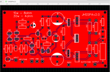
Hi, this is an amplifier I designed a while ago in conjunction with a few members here on the forum. I finally got around to putting it on the PCB and it does not seem to work.
I used 8050, 8055, BD139, BD140, TIP41, TIP42 transistors and running +/- 20v into a 8 ohm speaker. It sounds very low output and very distorted but when I disconnect power there seems to be a volume boost.
I ran the sim at 2 ohms load (I think its more realistic for a speaker?) and found omitting the output transistors emitter resistors improved stability but did not help the sound quality when I modified the board.
Any thoughts?
Attachments
Does EasyEDA do physical checks?
Probably not, otherwise you would have noticed that +20 doesn't make it over to the output transistors. Unless you were planning to use flying leads.
Some aspects of this layout are knot gud:
* Big output current loops - always route V+, V- and GND next to each other to minimize their area. Good layouts basically are "inside out". They're often elongated jobs running along the heatsink.
* No provisions for a shared heatsink. (Thermal stability would thank you.)
* Cluttered ground fills with loops included.
Last edited:
a) The output transistors do not have emitter resistors. Such resistors help to delay the onset of thermal runaway and also provide some negative feedback with its benefits.
b) The negative feedback chain electrolytic is only 10uF. You can increase this to improve the amplifier's low frequency response. Be aware most hearing information is in the first couple of kilohertz. You can try to use a 1000uF or even 2200uF for this.
c) The bias currents are too high according to LTSpice which calculates a current of 145mA. With this current you are continuously putting 20*0.145 = 2.9W. This makes the use of a heatsink a must, even without a signal.
d) The THD according to LTSpice is 0.473%. You can aim to reduce this.
e) The VAS's standing current is 17mA. Do you need this much. What happens if you use less?
f) The differential pair's standing current is 1.87mA. This is somewhat low. Usually, this is more like 2.5mA to 6.0mA.
Last edited:
Sure seems hot enough to me for an undegenerated BJT input. I'd actually consider 1-2 mA a fairly normal range.f) The differential pair's standing current is 1.87mA. This is somewhat low. Usually, this is more like 2.5mA to 6.0mA.
You can add g) - not only are the outputs running hot, but so are the drivers @ 80 mA a pop. I'd try 6 mA, maybe 12.
Blame the world renowned amplifier designer Douglas Self for that: it is in his book.sgrossklass said:Sure seems hot enough to me for an undegenerated BJT input. I'd actually consider 1-2 mA a fairly normal range.edbarx said:f)The differential pair's standing current is 1.87mA. This is somewhat low. Usually, this is more like 2.5mA to 6.0mA.
Post Scriptum:
In the VAS and input stage you have a substantial modulation of the standing currents. Try to reduce those.
The VAS's 'constant' current varies between 14.8mA and 15.8mA and the input stage's 'constant' current varies between 1.78mA and 1.97mA.
Last edited:
After I supplied a viable circuit, you got a lot of bad advice from others so the circuit has been butchered badly. I should have intervened but I was just disgusted so I kept silent, sorry. Never the less, it should still work, if badly.
If the circuit does not work at all then the possibilities are:
1. The prototype is not as advertised, ie mistakes were made in the assembly and it is impossible for us to guess what mistakes you may have made. Look for parts in backwards and the wrong parts in the wrong location.
2. The pin-out of your transistors may not be correct, ie emitter swapped with collector etc.
3. With no emitter resistors and likely over biased, one or more outputs may have died a fraction of a second after you power the circuit. Any newly built or repaired amp has to be carefully powered up with some kind of current limiting like lamps or resistors in series with the power supply rails.
Since you abandoned the auto-bias circuit, one of the resistors on the bias VBE multiplier should be a pot so that you can tweak the bias very carefully to avoid over-bias. Since the layout references and the simulation references do not match, I can't list them.
You changed the cross-coupler resistor+capacitor to two very small BE resistors. This means you took bad advise from someone who does not understand cross-coupling.
The VAS current source is unnecessarily too high from using a 38 Ohm resistor. About 10mA should be sufficient for a small amp like this, ie about 65 (68) Ohms.
I could go on but the original circuit was carefully considered and that's where you should have started from, and then when you got that working then you are free to try any "improvements".
Bad advice, by whom? Bad advice is against the rules. If you are certain about it, report and insist such users are permanently banned.
Bad advice, by whom? Bad advice is against the rules. If you are certain about it, report and insist such users are permanently banned.
Are you joking? This would reduce the number of members here to a tiny residual😛
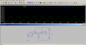
Here's my attempt at getting some sanity into the simulation.
Surprisingly enough, it suddenly starts behaving itself.
R5 should really be something like 750-820R + 200R pot in series, otherwise you may need a stack of E96 resistor values.
mod2 uses the luxury of BC550 input transistors.
Surprisingly enough, it suddenly starts behaving itself.
R5 should really be something like 750-820R + 200R pot in series, otherwise you may need a stack of E96 resistor values.
mod2 uses the luxury of BC550 input transistors.
Attachments
Last edited:
Are you joking? This would reduce the number of members here to a tiny residual😛
Well put! There is no law against bad taste and poor choices.
Here's my attempt at getting some sanity into the simulation.
Surprisingly enough, it suddenly starts behaving itself.
R5 should really be something like 750-820R + 200R pot in series, otherwise you may need a stack of E96 resistor values.
mod2 uses the luxury of BC550 input transistors.
Mirror needs degeneration too. 200mV will do, more is better though.
... and you expect such an immature and puerile personal attack to have effect!Are you joking? This would reduce the number of members here to a tiny residual😛
It is clear a good percentage of members have strong elitist tendencies, even though, they know this forum is open for all. They are irritated by anyone not using their select technical terms, otherwise, whoever posts on these fora is seen as inferior and ignorant of any technical knowledge.
The input stage of the circuit first posted in this thread is not functioning properly. The entire signal current is modulating the current source's current which should be constant. Moreover, the signal phases at the inverting and non-inverting inputs are almost equal. This violates the requirement that the current in both sides of the differential pair collectors always adds up to the same constant.
And you have the arrogance and pseudo-authority to throw mud.
Attachments
Last edited:
Mirror needs degeneration too. 200mV will do, more is better though.
Agreed, but not too much because you can get bad behaviours outside the normal operating conditions, and you want to keep the mirror transistors as far away from early saturation as possible. I developed this circuit much further and I used only about 100mV. This is enough if the VAS is not degenerated, because that compromises voltage swing and the OLG.
I am tempted to share the results but I'm not sure I want to share all my "secrets" (LOL). I will say that I abandoned current sources completely because a current source in the LTP makes almost zero difference in performance and a bootstrap in the VAS is better for voltage swing, and THD is almost as good as a current source.
This thread demonstrate the real problem of understanding priorities. Are we designing a cheap and simple practical circuit or are we trying to compete with the finest audiophile equipment? So many people focus on some achedemic point or feature and never step back and ask, but does it matter in this case. It's a classic mistake for students to attempt to build a monster kilowatt amplifier when they are barely capable of assembling a chip amp. Besides being a virtual guarantee of failure, nobody actually needs a monster amp in their home, so successful or not, it is soon relegated to storage and eventually the trash/recycle.
I am tempted to share the results but I'm not sure I want to share all my "secrets" (LOL). I will say that I abandoned current sources completely because a current source in the LTP makes almost zero difference in performance and a bootstrap in the VAS is better for voltage swing, and THD is almost as good as a current source.
Come on Steveu! Share your "Secrets", I am very interested on seeing new ideas.
May I politely ask: Why should any visitor of these fora want to exceed performance of equipment often costing in the range of tens of thousand Euros? That is unrealistic for many people including very qualified persons. I dare say, that is also hardly definable as DIY.steveu said:This thread demonstrate the real problem of understanding priorities. Are we designing a cheap and simple practical circuit or are we trying to compete with the finest audiophile equipment?
If a feature or capability qualifies as 'academic', it means there is empirical evidence proving its advantages.So many people focus on some achedemic point or feature and never step back and ask, but does it matter in this case.
First of all, I am not a student, secondly, I understand and know what it involves to assemble a chip amplifier. Right now, I have a stereo amplifier based on the chip LM3886 playing music. Although, the main PCB was inverted and the chip pads were 200% the required size, I succeeded to workaround those problems. I used adapter PCBs and the resultant assembly is physically robust.It's a classic mistake for students to attempt to build a monster kilowatt amplifier when they are barely capable of assembling a chip amp.
A monster amplifier like the one I made can easily be operated off a reduced voltage. 50V per rail are enough, which means, with its toroidal transformer, I need a 120V ac supply. The added benefit is, due to its size, it will never overheat even if it runs for an entire day. I tried this and I am very satisfied with the result. Other amplifiers will run far hotter.Besides being a virtual guarantee of failure, nobody actually needs a monster amp in their home, so successful or not, it is soon relegated to storage and eventually the trash/recycle.
Last edited:
May I politely ask: Why should any visitor of these fora want to exceed performance of equipment often costing in the range of tens of thousand Euros? That is unrealistic for many people including very qualified persons. I dare say, that is also hardly definable as DIY.
Hi Ed, not sure if the question is rhetorical, but many of the designs in this forum exceed the performance of commercial designs costing thousands of dollars/euros. In this video I compared a McIntosh to the HoneyBadger, and show comparable performance even though the former is ~5K USD and the latter maybe ~1k USD tops or less with a pretty cabinet, toroid, etc.
YouTube
(NOTE: The audio is a bit poor on this video, but it got better in the sub-subsequent ones)
Also, can you share schematics of your designs? I am always interested in looking at new stuff.
Best, Sandro
I got around to some sim and research but didn't want to open a dead thread. sgrossklass you nailed down my quick solution to needing higher hfe transistors on the input, so my final question before I design board v2.5 is could I use 2 sets of darlington pairs (replacing the input pair) to solve this problem? its seems like it would be real noisy though, could I use high gain signal trannies like the BC550C for all the low power transistors?
I like the idea of just adding 2 more jellybean transistors as the idea is to be able to use whatever is on hand (I.E. that 500 pack of 3904s you planned on building logic gates with)
Also thanks very much to everyone else who added suggestions to wich I'm implementing as needed.
I like the idea of just adding 2 more jellybean transistors as the idea is to be able to use whatever is on hand (I.E. that 500 pack of 3904s you planned on building logic gates with)
Also thanks very much to everyone else who added suggestions to wich I'm implementing as needed.
Also, I didn't mean to brew up such academic discussions. I did crutch alot on members of this forum who knew alot more than me and by doing so I also requested how they would deal this the proposition in the scenario they would use it in. Beyond "8 ohm 15 beans cheap parts" how can we all imagine the same application?
I value everyones input regardless of if they are Hi-fi- pomps or just able to get THD down below noticeable levels. For the learning like I it is all useful information.
I value everyones input regardless of if they are Hi-fi- pomps or just able to get THD down below noticeable levels. For the learning like I it is all useful information.
Does physical checks?
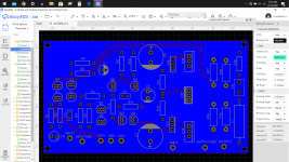
Two ways to check layout.
1/ Forward annotate and see if any changes are made.
2/ Run integrity check to look for differences between sch and pcb.
- Home
- Amplifiers
- Solid State
- Transistor power amplifier problem