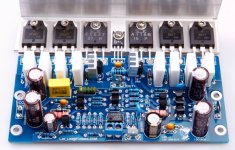
so the L25 board from eBay got delivered and I compared the item picture to what I received.

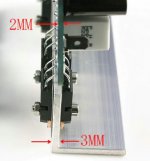
some components were different styles (no issue), the four large electros are 220uF instead of 150uF (probably not big issue?) but the biggest thing is the missing heat sinks on two of the smaller transistors.

in the original pictures the mini-heatsinks seem to be attached simply with white compound & the faces om the transistors on my board seem to have been sanded to form a rough surface.
so I am sure these are be required for proper operation without letting any smoke escape...
I have found self-adhesive ones: H0600 Mini PLCC Chip Adhesive Backed Heatsink - 10 x 10 x 10mm - Altronics
do these seem OK to use?
also - I am mounting on a bigger heatsink, should I reuse the soft transistor pads that came with it - or get new ones? also can I add some PC CPU paste to each one to improve the thermal transfer?

some components were different styles (no issue), the four large electros are 220uF instead of 150uF (probably not big issue?) but the biggest thing is the missing heat sinks on two of the smaller transistors.
in the original pictures the mini-heatsinks seem to be attached simply with white compound & the faces om the transistors on my board seem to have been sanded to form a rough surface.
so I am sure these are be required for proper operation without letting any smoke escape...
I have found self-adhesive ones: H0600 Mini PLCC Chip Adhesive Backed Heatsink - 10 x 10 x 10mm - Altronics
do these seem OK to use?
also - I am mounting on a bigger heatsink, should I reuse the soft transistor pads that came with it - or get new ones? also can I add some PC CPU paste to each one to improve the thermal transfer?
Attachments
I'd be more worried that the power devices are counterfeit.
assuming the mosfets are not fake, will the 10x10x10mm self adhesive heatsink I linked to be fine?
and also if i power it up, will they get too hot without a heatsink, regardless of whether am driving a speaker?
Last edited:
Should be ok to test, just see whether they get hot. If they get too hot to touch, they can probably use a heatsink.
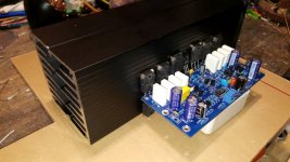
Just a note - the intent is that you attach the piece of angle aluminium which the outputs are tied down to onto the actual heatsink. This makes life easier and better supports the PCB physically.
I second the concern about counterfeit outputs... If it doesn't work as it should, that would be one of the first things to check.
Should be ok to test, just see whether they get hot. If they get too hot to touch, they can probably use a heatsink.
Ok, thanks!
OK, I see - yes, makes it seems to make it easier but isn't it less ideal for heat transfer? the power devices literally sit back to back?Just a note - the intent is that you attach the piece of angle aluminium which the outputs are tied down to onto the actual heatsink. This makes life easier and better supports the PCB physically.
I am going to support the PCB with stand-offs either way.
yes, gotta love the eBay "get exactly what you ordered, or your money back" policy!I second the concern about counterfeit outputs... If it doesn't work as it should, that would be one of the first things to check.
if this does not work, ill just get an ESP P68 board and build from scratch.
Attachments
Last edited:
The heat transfer only has to be sufficient, and it should be through the angle aluminium.
Ok, i wasn't really sure - it just looked quite weird having them back-to-back like that!
it will certainly mean less drilling and thread tapping! I had really only read one direct comment about this issue:
LJM L25 Clone modules
so i guess i was just basing this on that one post, plus a few other random pics I have found of this amp in real builds...
Last edited:
Seems from that thread that it's not adequate after all [emoji28] my bad. That's pretty rubbish design.Ok, i wasn't really sure - it just looked quite weird having them back-to-back like that!
it will certainly mean less drilling and thread tapping! I had really only read one direct comment about this issue:
LJM L25 Clone modules
so i guess i was just basing this on that one post, plus a few other random pics I have found of this amp in real builds...
assuming the mosfets are not fake
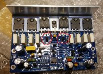
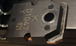
What MOSFETs? I see 2SA1186, 2SC2837, 2SD1047, 2SB817
And they look like they are re-marked fairly crudely, so probably fake/reject/recycled BJTs I'm afraid - sanded and black-coated, laser etched. Try rubbing
them with IPA on a Q-tip for 30 seconds and see if the black colour rubs off....
Try rubbing them with IPA on a Q-tip for 30 seconds and see if the black colour rubs off....
I rubbed and I rubbed, but no genie came out - nothing on the tissue either?
could you please post up the pictures of the genuine ones you are comparing these to? that would certainly help in getting a eBay refund!
or are you just comparing them to the original picture I posted, with the dark shiny square where the printing is placed?? they do look quite different...
Attachments
Last edited:
What MOSFETs? I see 2SA1186, 2SC2837, 2SD1047, 2SB817
And they look like they are re-marked fairly crudely, so probably fake/reject/recycled BJTs I'm afraid - sanded and black-coated, laser etched. Try rubbing
them with IPA on a Q-tip for 30 seconds and see if the black colour rubs off....
I don’t see how one can make a conclusion that the power BJTs are crude counterfeits based solely on a grainy picture where you can’t even see the mold markings inside the tiny circles in front.
Here are the KEC marking guide for the still active KTD1047 and KTB817
https://www.kec.co.kr/data/databook/pdf/mkg/eng/M ktd1047.pdf
https://www.kec.co.kr/data/databook/pdf/mkg/eng/M ktb817.pdf
well, the seller has replied regarding the different output device markings:
"Manufacturer may use different (from the picture) but same grade components "
and the missing heatsinks:
"the manufacturer has updated the design and the new bulk has not included the little heatsinks, they are not must, and that won’t influence the item’s performance."
But I think I'll still be checking the transistors temp before going too far! the design can't have change that much...
Here are the KEC marking guide for the still active KTD1047 and KTB817
thanks, that was helpful!
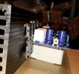
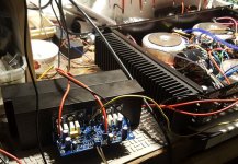
so I fired it up last night and everything seems fine.
just put a dumpster speaker on it but played for 20 mins at medium levels and seemed to last the distance.
the heat sink warmed slightly, but didn't have the fan hooked up.

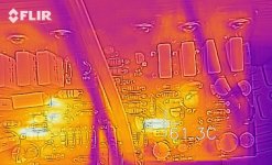
I put the FLIR camera on it and seems that the smallest transistors (labeled 5401) on the LHS of the amplifier were getting the hottest @ around 60'C

the other transistors on the RHS of the board (547 & 5551) were less hot.
but the transistors at the back that were missing the heat sinks barely got hot at all - which is great!
also - the large 3.3k resistors (which must be a 3W ones?) got well over 60'C - is that getting too hot? what is their purpose?
just put a dumpster speaker on it but played for 20 mins at medium levels and seemed to last the distance.
the heat sink warmed slightly, but didn't have the fan hooked up.
I put the FLIR camera on it and seems that the smallest transistors (labeled 5401) on the LHS of the amplifier were getting the hottest @ around 60'C
the other transistors on the RHS of the board (547 & 5551) were less hot.
but the transistors at the back that were missing the heat sinks barely got hot at all - which is great!
also - the large 3.3k resistors (which must be a 3W ones?) got well over 60'C - is that getting too hot? what is their purpose?
Attachments
- Home
- Amplifiers
- Solid State
- eBay L25 by LJM: missing transistor heatsinks?