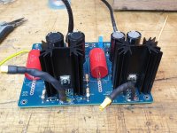
I have purchase the Broskie PS1 HV-LV power supply and am having issues with the HV side. I have sent a couple of emails to the John but have not received any response so I was hoping someone could assist.
The issue I have is, every time I apply the ac voltage to the boards ac input I get sparking at the base of the LD1085V regulator and it ends up passing the whole DC voltage to the output.
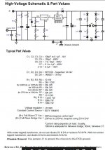
The circuit looks simple but I’m even simpler when it comes to understanding these circuits. John say the “The PS-1 regulator uses an LD1085 as the voltage regulator and an IXCY 10M45S constant-current source to shield the LD1085 from the high-voltage. The LD1085 is nested in its low-voltage span of just a few volts, while the IXCY 10M45S sees the bulk of the input/output voltage differential. Consequently, the IXCY 10M45S gets the heatsink, while the LT1085 is left naked.” But in my case, this doesn’t seem to be working.
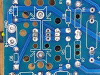
I have checked every component numerous times and they all seem to be fine, resistor are the right value, diodes and capacitors are the right way around, diodes are still good etc. D5 is missing in one of the images but that’s because I took it out to test it.
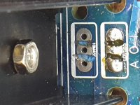
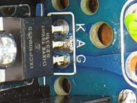
The board came with the obvious after production work to the area where the LD1085 & IXCY 10M45S are located, the vias have been cut way to stop them touching. I only noticed today that there is a little bit of copper showing where the alternate mounting location is for the IXCY 10M45S, but there isn’t a dead short between the 3 via’s. See image HV 4. I removed the LD1085 (it was dead anyway) to take the photo. I have left the IXCY 10M45S in place hoping it is still ok.
After removing the LD1085 I have measured between the IXCY 10M45S terminal in the hope that these measurements might mean something to someone wiser than I.
A-K = 21ohms = Is this too low?
A-G = 18.3mohms
K-G = 18.3mohms
I’m wondering if the 300ish volts could be arching due to the work around the via’s?
All thoughts/help is greatly appreciated.
The issue I have is, every time I apply the ac voltage to the boards ac input I get sparking at the base of the LD1085V regulator and it ends up passing the whole DC voltage to the output.
The circuit looks simple but I’m even simpler when it comes to understanding these circuits. John say the “The PS-1 regulator uses an LD1085 as the voltage regulator and an IXCY 10M45S constant-current source to shield the LD1085 from the high-voltage. The LD1085 is nested in its low-voltage span of just a few volts, while the IXCY 10M45S sees the bulk of the input/output voltage differential. Consequently, the IXCY 10M45S gets the heatsink, while the LT1085 is left naked.” But in my case, this doesn’t seem to be working.
I have checked every component numerous times and they all seem to be fine, resistor are the right value, diodes and capacitors are the right way around, diodes are still good etc. D5 is missing in one of the images but that’s because I took it out to test it.
The board came with the obvious after production work to the area where the LD1085 & IXCY 10M45S are located, the vias have been cut way to stop them touching. I only noticed today that there is a little bit of copper showing where the alternate mounting location is for the IXCY 10M45S, but there isn’t a dead short between the 3 via’s. See image HV 4. I removed the LD1085 (it was dead anyway) to take the photo. I have left the IXCY 10M45S in place hoping it is still ok.
After removing the LD1085 I have measured between the IXCY 10M45S terminal in the hope that these measurements might mean something to someone wiser than I.
A-K = 21ohms = Is this too low?
A-G = 18.3mohms
K-G = 18.3mohms
I’m wondering if the 300ish volts could be arching due to the work around the via’s?
All thoughts/help is greatly appreciated.
Attachments
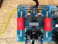
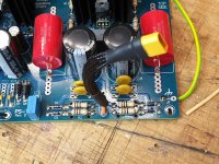
Looking at the pictures and the schematic, i get the impression that C7 and R8 are not connected to each other.
Looking at the pictures and the schematic, i get the impression that C7 and R8 are not connected to each other.
Hmmm, thanks for the sharp eyes, I will have a closer look when I get home. C7 has several mounting options but I never checked that they were all connected together, I will be suprised/annoyed if they are not 🙂
I'd worry about that 21 ohms also. With the design defect and Dremel treatment,
the boards should have been either scrapped or sold at a reduced price with a disclaimer.
Normally, the center lead should be jogged away from the heat sink (with the pads
in a triangle), for proper HV clearance.
the boards should have been either scrapped or sold at a reduced price with a disclaimer.
Normally, the center lead should be jogged away from the heat sink (with the pads
in a triangle), for proper HV clearance.
Last edited:
John has got back to me so we should be able to resolve the issue from here, turns out I sent my emails to an address that receives a lot of spam and I got lost in the mess.
I'd worry about that 21 ohms also. With the design defect and Dremel treatment,
the boards should have been either scrapped or sold at a reduced price with a disclaimer.
Normally, the center lead should be jogged away from the heat sink (with the pads
in a triangle), for proper HV clearance.
If necessary John has offered to send me a completed and tested board.
If necessary John has offered to send me a completed and tested board.
I would definitely take him up on that. Very much the right thing to do.
A-K = 21ohms = Is this too low?
A-G = 18.3mohms
K-G = 18.3mohms
18.3 milliohms is a dead short. Confusing milli / micro / mega is worth avoiding - learn the correct prefixes or confusion and misunderstanding will follow you around 🙂
All good John is replacing the lot.
You mean he is Dremel-ing on it as we speak? ;-)
Jan
You mean he is Dremel-ing on it as we speak? ;-)
Jan
No thats not what I meant 🙂
It's worth notng I bought this kit 4ish years ago and have only just got to it 🙂
1 confusion and misunderstanding will follow you around 🙂
You got that right😀
- Home
- Amplifiers
- Tubes / Valves
- Tube HV PSU Issue