I've got a Sony STR-DN1060 which blew one of the FL channel transistors the other week. I've replaced the pair and the matched double ceramic resistor. Put it back together and I'm still getting a protector error after about 10s.
I have the schematics for it. I've stripped it back down (repeatedly) and checked the resistances across the resitors in the current detector circuit on that channel (R1700-R1719), all look ok. I've checked the fuses (all OK), and D1700 and 1701, also check OK.
Any ideas for where to go next please?
I have (re-)checked the replaced transistors, and they aren't dead-shorts. Not checked them for a day or 2, but can do again. I've not measured the output DC offset, reaching the end of my experience, please can you explain how to?
Thanks
Paul
Thanks
Paul
You can measure DC offset anywhere from midpoint of the 0.22 ohm resistors to output inductor, Zobel network resistor to protection relay input - depending on what's easiest to reach. You are looking for a DC voltage to ground, which should be within +/-100 mV if the amplifier is operating normally.
When an output transistor has gone up, typical further damage includes:
* corresponding driver transistor
* input LTP transistor on the feedback side
* electrolytic cap in ground leg of feedback network (often a very low-voltage part of several hundred µF)
Might be one of the latter two. If you cannot find anything, look for any other components that measure out of the ordinary, like shorted diodes.
Once you find the remaining fault(s), be sure to check and adjust output transistor bias. Things usually don't blow up by themselves.
Thanks, I'll try that next. Is the driver transistor Q1375? Service manual is here: https://riverparkinc.com/wp-content/uploads/2015/05/strdn860_service_manuals.pdf and pages 64 and 65 show the relevant areas.
Appreciate your help
Paul
Appreciate your help
Paul
Interesting. Going by the schematic style, if I didn't know it was a Sony, I would've said it's a Kenwood. Our old 2005 Kenwood had very similar-looking power amps and schematic drawing style.
It's a Darlington output affair, so no discrete drivers.
Suspect capacitor: C1713 (220µ/10V)
Also check R1738 & R1739.
The style of this schematic is really confusing.
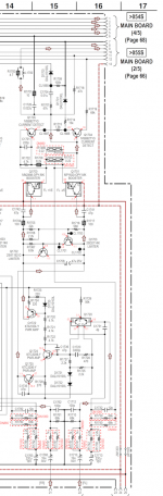
Double transistor Q1720 is the input LTP.
Then it goes into another differential amp made up of Q1724, 1725 with current mirror D1720-R1723-Q1722-R1724.
The output is coupled out of that, Hitachi style. The "limiter" transistors Q1702, 1703 have got to be the bias spreader, I don't see any other good candidates.
This kind of topology (though originally not with monolithic Darlingtons) has been around in Japanese gear since about 1977.
It's a Darlington output affair, so no discrete drivers.
Suspect capacitor: C1713 (220µ/10V)
Also check R1738 & R1739.
The style of this schematic is really confusing.
Double transistor Q1720 is the input LTP.
Then it goes into another differential amp made up of Q1724, 1725 with current mirror D1720-R1723-Q1722-R1724.
The output is coupled out of that, Hitachi style. The "limiter" transistors Q1702, 1703 have got to be the bias spreader, I don't see any other good candidates.
This kind of topology (though originally not with monolithic Darlingtons) has been around in Japanese gear since about 1977.
Attachments
Appreciate you taking the time to look at the schematic. I'll check all of those tonight / tomorrow; they're not ones I've checked so far.
Glad it's not just me that found it hard going
Glad it's not just me that found it hard going
Home late last night. Tested c1713 in circuit and it's resistance didn't rise to infinity in the way they normally do. So I figured you were probably right and it was duff and took it out of circuit. Tested it again and it's now fine... I'll try and work on the rest later tonight unless that points you in a direction of a problem.
Thanks Paul
Thanks Paul
- Home
- Amplifiers
- Solid State
- Sony Str-DN-1060 Replaced transistors still in protect