I've been using op-amps to boost signal from my sound card to test low-sensitivity tube drivers, and have been very impressed with how the particular op-amps I have been using have performed, very low distortion and what distortion was there was 2nd and a tiny bit of 3rd.
I've found that the most objectionable shortcoming of my tube amp is noise, not distortion. I've paired it with some pretty high efficiency speakers and have had difficulty getting things very quiet. The first problem I fixed was ground noise by installing input transformers. I also had a lot of weird noises coupled into the ground when I connected to a PC. I fixed that by installing an opto-isolator device in the USB connection between the audio adapter and the PC. Phew.
Now I'm down to just hiss, but more of it than I'd like.
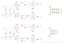
I designed the following input board to 1) reduce the overall gain of the amp (I have more than necessary) and 2) just try to do better at low-noise design in the first stage.
The board is fed by the output of the Jensen input transformer (hence the RC) and goes to an LM4562 stage that is similar to the input stage of an instrumentation amp setup. I chose the LM4562 because it has low distortion, good noise performance, and can drive heavier loads so I can choose resistances that will keep noise down. I also chose it because it does particularly well at keeping distortion down with large common-mode input swings; most op-amps do not do that well. It is well-suited to non-inverted duty. With +-17V supplies, it will put out 10Vrms with very low distortion, which is all I need right now.
I put the option of a second stage ADA4700 for later use (I have a new driver idea with less gain, so I might need more up front). The ADA4700 can get me from 10Vrms to 30Vrms. It has more distortion than the LM4562 but is the lowest distortion amp I can find that can handle voltages this high. I also put a trimmer as an AC balance adjustment. The amp this is going into has no global feedback loop so nulling out the 2nd harmonic generated in later stages has a big effect on lowering overall distortion. Of course, if the trimmer is not desired in another application, I can install a jumper wire and bypass it.
Anyway, what do you guys think of this heresy? Anybody see anything major or minor that I'm missing in this approach? I'm sort of new to this op-amp design stuff, having only read Douglas Self's small signal audio design book, and he doesn't exactly cover the best ways to drive tube circuits with op-amps.
I've found that the most objectionable shortcoming of my tube amp is noise, not distortion. I've paired it with some pretty high efficiency speakers and have had difficulty getting things very quiet. The first problem I fixed was ground noise by installing input transformers. I also had a lot of weird noises coupled into the ground when I connected to a PC. I fixed that by installing an opto-isolator device in the USB connection between the audio adapter and the PC. Phew.
Now I'm down to just hiss, but more of it than I'd like.
I designed the following input board to 1) reduce the overall gain of the amp (I have more than necessary) and 2) just try to do better at low-noise design in the first stage.
The board is fed by the output of the Jensen input transformer (hence the RC) and goes to an LM4562 stage that is similar to the input stage of an instrumentation amp setup. I chose the LM4562 because it has low distortion, good noise performance, and can drive heavier loads so I can choose resistances that will keep noise down. I also chose it because it does particularly well at keeping distortion down with large common-mode input swings; most op-amps do not do that well. It is well-suited to non-inverted duty. With +-17V supplies, it will put out 10Vrms with very low distortion, which is all I need right now.
I put the option of a second stage ADA4700 for later use (I have a new driver idea with less gain, so I might need more up front). The ADA4700 can get me from 10Vrms to 30Vrms. It has more distortion than the LM4562 but is the lowest distortion amp I can find that can handle voltages this high. I also put a trimmer as an AC balance adjustment. The amp this is going into has no global feedback loop so nulling out the 2nd harmonic generated in later stages has a big effect on lowering overall distortion. Of course, if the trimmer is not desired in another application, I can install a jumper wire and bypass it.
Anyway, what do you guys think of this heresy? Anybody see anything major or minor that I'm missing in this approach? I'm sort of new to this op-amp design stuff, having only read Douglas Self's small signal audio design book, and he doesn't exactly cover the best ways to drive tube circuits with op-amps.
Attachments
Why have tubes after all this glorious perfection? There are projects at this site using compound chip amps that have harmonic distortion approaching the absolute zero. I get weak at the knees just thinking about it.
Why have tubes after all this glorious perfection? There are projects at this site using compound chip amps that have harmonic distortion approaching the absolute zero. I get weak at the knees just thinking about it.
Because it will be a component in an existing tube amp. As stated above. 🙄
Imo it will be a major determining factor for the sonics. Getting rid of hum and hiss in a tube input stage is trivial and cannot be an excuse.
Imo it will be a major determining factor for the sonics. Getting rid of hum and hiss in a tube input stage is trivial and cannot be an excuse.
Okay, thanks for the advice. It isn't the path I'm taking.
What is the purpose of the pot in the lower half? To adjust out any imbalance from the source?
No, it is to purposely introduce an adjustable amount of imbalance to cancel out gain imbalance in the later tube stages. This feature could be easily bypassed by soldering in a jumper wire in place of the trimmer and just using equal resistors.
The amplifier this is going into has far more H2 distortion than any other harmonic, just due to driver tube gain differences between the sides (I'm using old 841 DHTs as the driver tube). This allows me to compensate for that imbalance if I want.
I like it. I’ve had some low-sensitivity amp ideas that I’ve thought about putting a SS gain stage in front of. I always lose interest when I think about integrating a second power supply.
I like it. I’ve had some low-sensitivity amp ideas that I’ve thought about putting a SS gain stage in front of. I always lose interest when I think about integrating a second power supply.
So, I already took out the tubes in this amp out to make room for the input transformers and have been running a SS first stage that is simply two ADA4700s configured like the first stage of this design. I power it with two Meanwell 48V isolated-output switching supplies to generate the +-48V. AC goes in, +-48V comes out. There is no discernible coupling of switching noise into the amp. For this one, I'm going to use LME49860 for the first stage and power it from +-18V generated similarly.
In this iteration, I'm going to try to design a filter for the output of the switching supplies to make them cleaner.
But that's precisely the intent here. I'm going to make a low-sensitivity tube amp that will have a shorter feedback loop and have a very low distortion SS preamp inside.
I think it would be more meaningful to post the design in full rather that just the front end. Even if you're more uncertain about the SS stage than the tube stage, you might get a comment you didn't foresee.
I make Guitar amps and in High Gain ones, I always use a 20X Op Amp at the input.
Very clean, silent and predictable, saves me from wasting hours and $$$$ selecting first stage tubes with a very low yield.
Also saves me from microphonics.
Very clean, silent and predictable, saves me from wasting hours and $$$$ selecting first stage tubes with a very low yield.
Also saves me from microphonics.
I think it would be more meaningful to post the design in full rather that just the front end. Even if you're more uncertain about the SS stage than the tube stage, you might get a comment you didn't foresee.
Here is a link to my writeup.
Output stage needs 160Vrms in. 841 stage needs 5.3Vrms in to develop 160Vrms. The plan is to use only the first stage of this SS board at first, which should be capable of 10Vrms with very low distortion from a 2V source.
Later, as my supply of 841s dwindles, I have plans to convert the driver to something like this. I will set it for less gain than the 841 and make up for it with the ADA4700 stage and have the ability to trim out gain imbalances. Distortion in the overall amp should be very low at that point. As it stands, the 841s are the dominant source of distortion in the amp but I'm in no rush to get rid of them because they are pretty.
I am also in the process of changing the supplies around on the 841s so that the grid circuit is referenced to ground, which may have some benefits as far as the hiss goes? I mean, I expect that the Maida regulator feeding that node has some noise at the output that is greater than it would be if referenced to ground, I just don't know how significant it is as far as overall noise contribution to the amp output.
I'm also planning on running some tests on alternative drivers for the 841 grid. Since it is operated in A2, even at fairly low signal levels, improving the grid driver performance may have a significant effect on overall amp distortion.
So that's where this fits in the overall scheme of things.
Unfortunately, I'm out of space in the input area of the amp so tubes are not going back in there. Plus, I'm having fun trying my hand at something that is new to me.
I do have some experience playing with and measuring these chips: See here for details.
nothing new here, wireless world posted such designs using discretes to drive kt88's..
http://www.keith-snook.info/wireles...76/Transistor driver for valve amplifiers.pdf
http://www.keith-snook.info/wireles...76/Transistor driver for valve amplifiers.pdf
Attachments
Last edited:
I go other way, tube input and class D output.
The arrangement allows murdering the Third with very low overall distortion.
Watch out for switching supplies. Verry tough to totally clean up.
I went back to linears. Op amps are ok with 120hz common mode but hate 100khz.
The arrangement allows murdering the Third with very low overall distortion.
Watch out for switching supplies. Verry tough to totally clean up.
I went back to linears. Op amps are ok with 120hz common mode but hate 100khz.
There's also a OPA453 which you can drive the grid of an output stage directly. By running the device off +5v and -75v you can get just the right grid swing to drive EL34's or 6550's. I have a 120W pp amp built like this and works just fine.
I go other way, tube input and class D output.
The arrangement allows murdering the Third with very low overall distortion.
Watch out for switching supplies. Verry tough to totally clean up.
I went back to linears. Op amps are ok with 120hz common mode but hate 100khz.
I plan on eventually building a linear supply but don't have the space at the moment. Other changes in the amp will eventually make the space I need. Also, I'm going to use LME49860 for the first stage instead of LM4562. Very similar but can accommodate up to +-22V rails. I'd like to get close to that and get as much headroom as I can, so a custom supply is in order.
In the meantime I'll have some fun trying to quiet some cheap switching 18V supplies down as much as I can.
There's also a OPA453 which you can drive the grid of an output stage directly. By running the device off +5v and -75v you can get just the right grid swing to drive EL34's or 6550's. I have a 120W pp amp built like this and works just fine.
Funny you mention that, I'm looking at improving the grid driver in my amp for the 841 tube, which requires grid current. Currently it uses a mosfet follower but I've thought about testing an op amp to see if it results in less distortion at the output of that stage. So far, the LME49860 looks like the best for that job that I have found but I've always got my eyes open for other options.
The 841 seems to be the biggest contributor to overall distortion in the amp, and I have always wondered if improving the grid drive would decrease distortion at all.
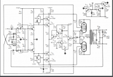
This is an amp I built recently. V4 is in fact 4 outputs of a DAC08 which allows the bias of each tube to be set separately. There's a one time calibration which measures the current in each tube at a time. The first stage is floating input to prevent hum loops. It may give you more inspiration for your ideas. The opa453 in not unity gain stable which is ideal for getting the voltage gain.

This is an amp I built recently. V4 is in fact 4 outputs of a DAC08 which allows the bias of each tube to be set separately. There's a one time calibration which measures the current in each tube at a time. The first stage is floating input to prevent hum loops. It may give you more inspiration for your ideas. The opa453 in not unity gain stable which is ideal for getting the voltage gain.
View attachment 816529
Ah very nice! I control the bias in my amps with a servo circuit. I also sample current at all four output tubes and there is a shutoff circuit in the even of that current gets higher than it should.
Recently, the amp I made for my brother started making some funny noises, so he sent it back to me. I took the tubes out and couldn't find anything wrong, so I put the tubes back in and the amp would run just fine for a few minutes and then started making crackling noises. I looked over at it and one of the tubes was flashing; it was arcing internally and then the amp just shut down. I moved the tubes around fired it back up. Same tube, same problem, different location. Each time the protection circuitry shut the amp down.
I dissected the tube and the cathode coating was separating from the cathode and falling onto the grid.
I made a couple of changes:
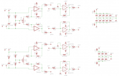
1) separated stages so I can just leave stage 2 completely unconnected and unpowered until used. I will put in a jumper when I eventually use it.
2) moved the AC (im)balance adjustment to the first stage so that it is useful in the first phase of my rollout of changes. I don't know why I didn't just put it there to start with. It looks much more symmetrical now.
I'll probably have this built as soon as I complete the layout changes.
Attachments
- Home
- Amplifiers
- Tubes / Valves
- SS Input Board for Tube Amps