
Much appreciated.
I don't have exactly 16v, but a higher ones. I think it will be fine with a higher ~v and same capacitance.
I don't have exactly 16v, but a higher ones. I think it will be fine with a higher ~v and same capacitance.
Is that the service manual for this amp?
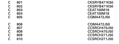
100uf is an odd value for that type of duty (looks like shunt to ground).
100uf is an odd value for that type of duty (looks like shunt to ground).
It is from the service manual. Pioneer do sometimes adjust their value suffixes but as it is from chassis to ground it doesn't matter on the value. It is only for shunting HF interference.
I will not share the manual as it is probably copyright.
I will not share the manual as it is probably copyright.
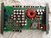
The problem is that amp is in protect and draws a lot of current making the PS Fets IRF3205 super hot in a seconds. I've already removed the output mosfets.
Checked every small SMD transistor and diode. Everything reads fine, the only odd thing were these two small smd caps....
There have been previous attempts for a repair but they were unsuccessfull ones.
Now after replacing these small caps, i'll remove the IRF3205 and check the gate drive...
Checked every small SMD transistor and diode. Everything reads fine, the only odd thing were these two small smd caps....
There have been previous attempts for a repair but they were unsuccessfull ones.
Now after replacing these small caps, i'll remove the IRF3205 and check the gate drive...
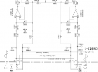
The diagram appears to have a conflict. The caps in the photo are clearly going to a ground point. The ones in your diagram are coupling capacitors with no connection to ground.
Good old Pioneer. Nothing changes. We were told about errors when we went on technical training days.
The ground point capacitors are only for noise reduction. There is no way that the capacitors are labelled correctly in the schematic.
The ground point capacitors are only for noise reduction. There is no way that the capacitors are labelled correctly in the schematic.
Replaced the caps.Tried to run it.
PS Fets gate drive looks like almost a straight line of DC, almost.
Power transformer puts out awful squeaky/buzzing sound and it pulls out as much current as i can supply.
I think there is a short inside of the transformer....
PS Fets gate drive looks like almost a straight line of DC, almost.
Power transformer puts out awful squeaky/buzzing sound and it pulls out as much current as i can supply.
I think there is a short inside of the transformer....
Tiny chip caps like that are certainly not electolytics.
Likely something like 0.01uf film types.
Likely something like 0.01uf film types.
Replaced the caps.Tried to run it.
PS Fets gate drive looks like almost a straight line of DC, almost.
Power transformer puts out awful squeaky/buzzing sound and it pulls out as much current as i can supply.
I think there is a short inside of the transformer....
Doubtful.
Disconnect it from the rectifiers and then test it for AC output.
You've got something wrong in the amp section.
The power supply drive has to be swinging between 12v and ground. Is the drive circuit pulling the drive signal to very near ground?
A photo with the scope on DC coupling would be helpful.
A photo with the scope on DC coupling would be helpful.
Pulled out the rectifiers. Same. The problem is in the PS section.
There is almost no swing between 12v and ground, it's like they are turned on at all time. No pulling to the ground.
All the small SMD transistors near TL494 read fine. Checked them one by one as I did for all the gate resistors and pull down resistors.
I still bet my money it's short in the transformer due to the fact amp was mounted on the subwoofer box.
I can post a picture of the gate drive a little bit later.
Perry is always right. With no PS FETS = perfect gate drive. When they are in - amp is in protect and pulls as much current as it can, like something is shorting out, but the only thing which gets hot are the PS FETS.
Already checked each one of them - they all read fine.
Interestingly enough it's the same with or without rectifiers, it doesn't matter if they are installed or not.
Already checked each one of them - they all read fine.
Interestingly enough it's the same with or without rectifiers, it doesn't matter if they are installed or not.
The drive signal doesn't generally have a problem with the FETs in the circuit, even if there is a problem down the line.
Check the FETs for leakage from the gate to the other terminals.
Did you try loading the drive circuit with a resistor or small capacitor to see if it is OK?
If you suspect the transformer, try twisting/pushing/pulling it while powering the amp through a limiter with all FETs clamped to the heatsink to see if the current draw changes.
Twisting/pushing/pulling the transformer - does not do anything.
FET's are reading fine using a transistor tester, but as far as I know they are not under load during the testing procedure, so i don't usually trust 100% to the transistor tester.
How to "load" the drive circuit ?!
FET's are reading fine using a transistor tester, but as far as I know they are not under load during the testing procedure, so i don't usually trust 100% to the transistor tester.
How to "load" the drive circuit ?!
- Home
- General Interest
- Car Audio
- Pioneer GM-D9601 burnt caps value ?!