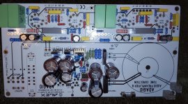
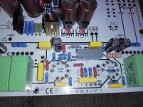
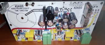
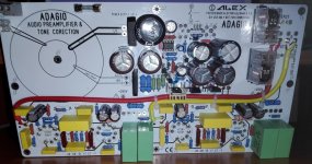
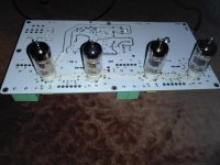
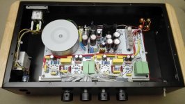
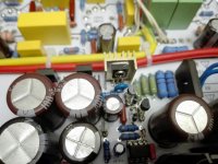
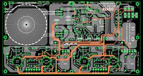
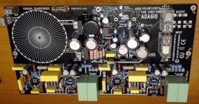
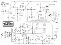
New year, new build,in progress, tone correction preamplifier with 12AX7EH schematic ADAGIO from Dr.Bora Jagodics (R.I.P.) . Second build this year .....
Regards,
Alex
Regards,
Alex
Attachments
-
 IMG_20190205_184135-001.jpg983.6 KB · Views: 1,216
 -
 IMG_20190205_184147-001.jpg864.4 KB · Views: 1,103
 -
 IMG_20190205_184214-001.jpg927.7 KB · Views: 936
 -
 IMG_20190205_184223-001.jpg844.5 KB · Views: 906
 -
 IMG_20190205_184235-001.jpg982.6 KB · Views: 830
 -
 IMG_20190205_184254-001.jpg981.9 KB · Views: 324
 -
 IMG_20190205_184302-001.jpg984.4 KB · Views: 350
 -
 IMG_20190205_184311-001.jpg1,000.3 KB · Views: 399
 -
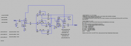
 ADAGIO SCHEMATIC.jpg162.1 KB · Views: 779


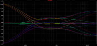
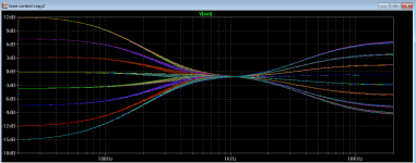
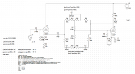
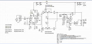
Hi "alex mm", I am been impressed by the schematic of your build so I put it on a simulator specially for the tone control, I built so far many tone control so I was curious, here the result.( 1st/2nd pic.) I think some adjustment are necessary because the target of a good tone control is have the audio taper potentiometers to get rather flat response when they are set halfway between maximum and minimum around 0 dB and you can see the Adagio is far away from it also there is really no one curve response flat in the middle of the plot and a lot of roll-off frequency.
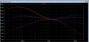
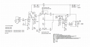
A good tone stack control should work like this ( Pic 3 & 4 ).
I build many tone control from the RCA schematic and so on but the one really achieve all goals I found in this website Practical Tone Controls.
Ltspice simulator work very well with tone control circuit, I recently built the 3 tone control propose in the website and the result is outstanding and as you can see simulation and real test are very close. ( Pic 5,6,7 )
Now I think the Adagio because can be used as a pre-amp without tone control or with tone control cannot really achieve a good performance because the first stage is not a cathode follower so with hight output impedance is very difficult but I think that some adjustment on the value of the component can just give some improvement. All the best
Attachments

Hi Kissabout 2002 ,
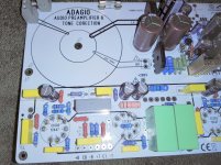
Thanks for your toughs , simulation, schematic . I will reconsider schematic, and I will try, some changes, in values of components to see how it works . This board it's a prototype and I agree for modified version. I'm not so good in theoretical things, I'm a hobbyist . Pictures from 2010 of first built tone correction. 🙂
Regards,
Alex
Attachments
 Posts moved from the Pictures Thread, please note that discussion of a specific build should be conducted in its own thread, and not in the Sticky thread.
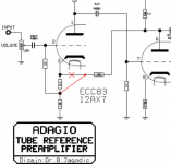
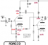
Hi, missing in Your sim: 100K, from V1b plate to V1a cathode.Hi "alex mm", I am been impressed by the schematic of your build so I put it on a simulator specially for the tone control, I built so far many tone control so I was curious, here the result.

Hi all ,
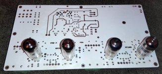
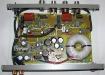
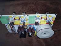
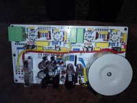
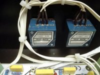
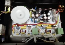
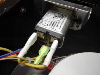
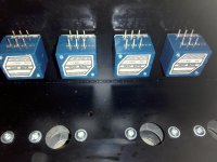
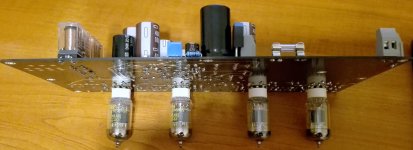
Transformer, mechanical adapted to PCB, it's shielded electrostatic and magnetic . Power supply, and timer, work fine, also muting, and by pass relay .
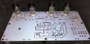
Tomorrow will test with tubes in circuit. 🙂
Regards,
Alex
Transformer, mechanical adapted to PCB, it's shielded electrostatic and magnetic . Power supply, and timer, work fine, also muting, and by pass relay .
Tomorrow will test with tubes in circuit. 🙂
Regards,
Alex
Attachments
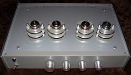
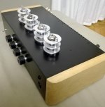
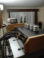
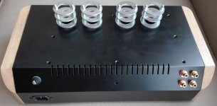
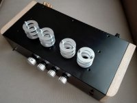
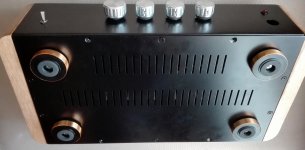
Tone correction preamplifier at final step. It's working, was tested, and now has new enclosure . More pic's tomorrow . 😀
Attachments
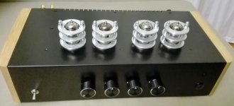

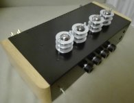
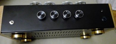
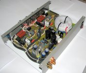
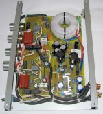
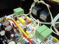
And inside pictures ....😀
Attachments
-
 IMG_20190228_211858 (2).jpg806.6 KB · Views: 134
 -
 IMG_20190228_211923 (2).jpg680.9 KB · Views: 142
 -
 IMG_20190228_211936 (2).jpg601.1 KB · Views: 128
 -
 IMG_20190228_212052 (2).jpg767.9 KB · Views: 137
 -
 IMG_20190228_212241 (2).jpg698.9 KB · Views: 146
 -
 IMG_20190228_212122 (2).jpg773.4 KB · Views: 153
 -
 IMG_20190228_225946.jpg339.8 KB · Views: 141
 -
 IMG_20190228_212024 (2).jpg610.2 KB · Views: 129
 -
 IMG_20190228_212004 (2).jpg676.7 KB · Views: 121
 -
 IMG_20190228_211948 (2).jpg531.6 KB · Views: 146
Very nice work and PCB. Do you have the Gerber files for the PCB?
Also, I sent you a PM couple of days ago.
Thanks!
Also, I sent you a PM couple of days ago.
Thanks!
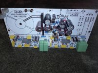
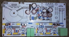
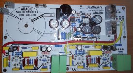
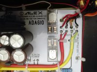
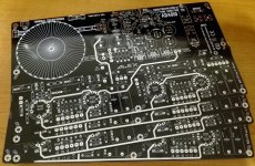
I try to build, a new tone correction, same schematic but new rev.3 PCB optimized tracks . Good quality components :Alps blue velvet pot's , Vishay propylene capacitors, 1% metalised resistors, shielded toroidal transformer (electrostatic and magnetic ) and selected highgrade 12 AX EH tubes.🙂
Regards,
Alex
Regards,
Alex
Attachments
-
 IMG_20190830_131013.jpg467.3 KB · Views: 162
 -
 IMG_20190830_131026.jpg496.8 KB · Views: 93
 -
 IMG_20190830_131049.jpg849.8 KB · Views: 76
 -
 IMG_20190830_131127.jpg532.3 KB · Views: 86
 -
 IMG_20190831_082123-001.jpg998.1 KB · Views: 123
 -
 IMG_20190906_233952-001.jpg998.5 KB · Views: 150
 -
 IMG_20190906_233918-001.jpg692.7 KB · Views: 152
 -
 IMG_20190906_233837-001.jpg479.4 KB · Views: 128
 -
 IMG_20190906_233857-001.jpg419.8 KB · Views: 138
 -
 ADAGIO SCHEMATIC.jpg162.1 KB · Views: 189
- Home
- Amplifiers
- Tubes / Valves
- ADAGIO from Dr. Bora Jagodics