Sorry to ask such an amateur question, but I want to be sure I understand the difference...I have read Thomas's nice article here:
VinylSavor: Gain, Headroom and Power
...hmmm...what confuses me from Thomas's article: "If the output tube needs 100V peak-peak for full power out, the driver stage should be designed such that it can deliver 200V peak-peak or more."
I guess I am taking his words in the wrong way, do we really want 200Vpp ? Or should it only in theory be capable to deliver this unconstrained...in case the input signal would be - completely hypothetically - doubled..? So gain is not changed at all.
Let's try to do a praticle example: - I am running a 300B PP at 450V at 6k and 55mA per tube. -Ug is around -100V. - For the right listening level with my speaker, I need 160Vpp at the grids of the 300Bs (no volume attenuator in the signal path, that the level I prefer for nearly all the music I listen to).
I do not need more gain than what I need to get 0Db from a DAC sinus to 160Vpp to the grid of the 300B. Why should my driver now deliver 320Vpp ?
What I would found more logical would be the following description (which is potentially whatThomas meant anyhow and I could not read it the right way):
"The headroom of a component or gain stage is the difference between the maximum input or output signal it actually receives or delivers( in my Case the needed 160Vpp) to the maximum undistorted input/output voltage envelope it could process flawless. (read: No grid current or voltage cut-off, in my case 200Vpp at the 300B grids).
...plus there are two headroom definitions to be taken care of, one on the input and one on the output side of each stage, right ?
Input-Side: If I need 160Vpp on the grid of the300B in terms of gain, it would be good to have some more -Ug voltage than only -80Voltage, so the difference between -80 and -100 which I actually use is the headroom.
Second example: The DAC chip delivers over its I/V-resistor maybe 2Vpp. Running the 801A at 350V/28mA gives us maybe -11V Ug, so we have 10V headroom on the input side.
Output-Side: We could as well have per stage a headroom on the output side and I guess that was what Thomas meant, so the 801A stage has only to produce 16Vpp output with an input of 2Vpp...with -11V Ug swing could go from 0V to 22V resulting in a swing from 230V to 400V=170Vpp...so a lot of headroom which theoretically could be process flawless as well on the output side, eben though this will never happen as the DAC only produces 2Vpp.
Correct ?
Last edited:
Headroom is just the amount of voltage left in a stage between signal and power supply when applying max input signal. If there isn't enough you will get distortion.
The trouble with transients is they can be much more than the average signal level so you need an amp with a good voltage headroom.
The trouble with transients is they can be much more than the average signal level so you need an amp with a good voltage headroom.
A barely-enough driver will have 5% THD at max output.
For high-gain power tubes, we usually design the driver for much-more output than required, so it will be working in a lower THD zone.
6L6 needing 20V peak drive might be run with a driver capable of 100V peak, so driver THD is more like 1%.
For low-gain 300B, 80V peak for full power would suggest a driver like 400V peak @ 5% THD to get 80V peak at 1% THD in the driver. This leads to a 2,000V supply for the driver. This is clearly inconvenient, costly, deadly.
And a simple triode driver, feeding a triode output, there is cancellation of the two distortion curves. For minimum final THD you want both stages working equally hard. However as always, cancelling simple 2nd harmonic will expose, even increase, the higher harmonics which annoy the ear more.
There's no perfect answer. Go with what makes sense. This usually means feeding driver nearly as much B+ as the power stage.
^what i learned from the postings of PRR, it would be be wise to follow his suggestions....
voltage gain and headroom are two different animals....
voltage gain and headroom are two different animals....
- I am running a 300B PP at 450V at 6k and 55mA per tube. -Ug is around -100V. - For the right listening level with my speaker, I need 160Vpp at the grids of the 300Bs (no volume attenuator in the signal path, that the level I prefer for nearly all the music I listen to).
Any amplifier should be constructed so that when driven to full output power, the output stage begins to clip first, and clip essentially earlier (at lower input signal) than any other stage of the amplifier.
To me it is peculiar to have "sufficient listening level" as a design goal. My design goal would be to get all the potential of 300B for use.
Well, that is the beauty of working with IT, I guess...there is always enough voltage swing/ there will not be a shortage of Power supply voltage for the signal, so only the other borderline to 0V/ grid current matters.
Example again: My EML20a are running at 420V on an IT in PP/LTP with 33mA each. -Ug is around -10.5V for a Vpp input signal max 16Vpp (technically more cant be delivered by the DAC-801A stage). With an RC load it might need 700V to get the job done.
Now to the aspects of transients: Nigel, you said they could be much higher than the normal signal. But they are part of the music signal, right ? So when I force a DAC to max. output by playing a sinus at 0db: Is this NOT the max signal it can produce ? That is what I thought.
I can understand that when you listening to music, the normal music signal might be at -18db and from time to time the transients jump up to the 0db level. But when you design from the beginning to the 0db level, are you not covered ? Can a DAC play louder than 0db ?
Well...why ?
If I do this, I need more gain, right ? Or, alternatively, I could lower the OPT impedance of the 300B and the 450 to 400V or even 350V and make it to clip earlier, run earlier out of class a, produce more distortion as lower primary impedance is always there etcetc....
More gain means, like Thomas described nicely:
- either more tube stages or
- worse impedance relations (e.g. using an input transformer)
- an attenuator which destroys the gain again.
I my case, I have after the DAC-chip only a directly coupled 801A-LTP-stage with an OPT, a eml20A-input-driver-stage with IT driving directly the "so hard to drive" 300B. Alternatively parallel 6sn7 work equally well (20mA, rp of 4k).
I clearl elieve in the concept of the less stages and less components needed which can mess up the music, the better...operating them with enough headroom. But ultimately you want only as much gain as necessary.
Example again: My EML20a are running at 420V on an IT in PP/LTP with 33mA each. -Ug is around -10.5V for a Vpp input signal max 16Vpp (technically more cant be delivered by the DAC-801A stage). With an RC load it might need 700V to get the job done.
Now to the aspects of transients: Nigel, you said they could be much higher than the normal signal. But they are part of the music signal, right ? So when I force a DAC to max. output by playing a sinus at 0db: Is this NOT the max signal it can produce ? That is what I thought.
I can understand that when you listening to music, the normal music signal might be at -18db and from time to time the transients jump up to the 0db level. But when you design from the beginning to the 0db level, are you not covered ? Can a DAC play louder than 0db ?
Any amplifier should be constructed so that when driven to full output power, the output stage begins to clip first, and clip essentially earlier (at lower input signal) than any other stage of the amplifier.
To me it is peculiar to have "sufficient listening level" as a design goal. My design goal would be to get all the potential of 300B for use.
Well...why ?
If I do this, I need more gain, right ? Or, alternatively, I could lower the OPT impedance of the 300B and the 450 to 400V or even 350V and make it to clip earlier, run earlier out of class a, produce more distortion as lower primary impedance is always there etcetc....
More gain means, like Thomas described nicely:
- either more tube stages or
- worse impedance relations (e.g. using an input transformer)
- an attenuator which destroys the gain again.
I my case, I have after the DAC-chip only a directly coupled 801A-LTP-stage with an OPT, a eml20A-input-driver-stage with IT driving directly the "so hard to drive" 300B. Alternatively parallel 6sn7 work equally well (20mA, rp of 4k).
I clearl elieve in the concept of the less stages and less components needed which can mess up the music, the better...operating them with enough headroom. But ultimately you want only as much gain as necessary.
Last edited:

artosalo,
A single ended amplifier that clips when the output tube current goes near to zero will completely loose control of the loudspeaker woofer (a very bad thing). So clipping the output stage first will not be a good choice in this case.
Of course, we should either get a more powerful amplifier; or we should turn the volume control down on the amp we have, so the amp is not clipping.
6A3sUMMER, I enjoy reading your posts - thanks for them/that.
What are your thoughts with regards to a B supply to the output stage which has a series CCS to a final shunt cap, in which case sets the idle current for the tube, provides a high PSRR and also a tight AC signal loop?.
I've tried CCS tail in a PP amp, but not plate side of a SE output, yet. Input and drivers, yes and it works very well.
To keep somewhat with the OP, I always felt that designing an amplifier so that the output clipped first would ensure full output power, I can't rationalise away from that.
On the gain vs headroom issue, surely it comes down to gain structure WRT operating points and ensuring that the input and driver are operating in a linear region of the transfer characteristics when delivering maximum swing to the output tube. You can have 400vp-p swing at the driver plate, but so what if the output clips at 160vp-p in, assume Class A1 only.
IMO swinging linear volts which clips the output stage first is all that is required on the amplitude side of things.
Hanze
Last edited:
Hanze Khronye,
I am glad you enjoy reading my posts. But be careful, I make mistakes. I usually try and correct them when someone shows me the correction.
Can you please post schematics of the circuits you mention in your first and second sentences of post #7? I want to be sure of exactly what the circuits are, before I answer.
But here is a generalization about most push pull amps: In a push pull amp, if one tube is at low current (High plate resistance, rp), the other tube is at high current (Low plate resistance, rp). Therefore, we have not fully lost control of the woofer.
I do use both SE and push pull amps.
Last edited:
6A3sUMMER,
Fortunate enough to be abroad at the moment, which is to say that I don't have access to my files or a scanner. Yes, my hotmail account has locked me out due to 'indifference', and they have their own procedures in place, which exclude me at this time.
Should be easy to illustrate with words. A CCS with low input capacities in lieu of a standard filter choke, in series with the B supply to the stage. A capacitor as final shunt element, after the CCS and across the supply, top of plate load to signal common, and that's all there is to it.
It works very well for voltage gain stages, but as for an output stage, I don't yet know.
My thoughts with regard to headroom stand (just to keep on topic) 😉
Regards,
Hanze
Last edited:
A single ended amplifier that clips when the output tube current goes near to zero will completely loose control of the loudspeaker woofer (a very bad thing). So clipping the output stage first will not be a good choice in this case.
Just keep on reading amplifier design basics.
Well...I think it is important to have a look on assumptions before making up static rules. As said earlier, I can easily make the output stage running to clip as the earliest as your rule suggested. Maybe I even produce more power or more gain.
But again: Why ?
The whole trick is to build the system towards the lowest gain at the lowest distortion needed / possible...which is what Nelson Pass has suggested as well when introducing the F4.
But again: Why ?
The whole trick is to build the system towards the lowest gain at the lowest distortion needed / possible...which is what Nelson Pass has suggested as well when introducing the F4.
Blitz,
Yes, I agree with PRR. We should have drivers that are capable of more voltage drive than the output stage needs, so that we can have low distortion drivers. But it is almost always a good idea to keep away from clipping, unless we are a Guitar Rock Star.
Well, you could design an SE amplifier output stage with Lots more standing current, and which only clips at the high current peaks of the signal, i.e. it draws grid current, and even with a very strong driver it has the grid going positive many volts versus the DH Filament, or Cathode. That way, the driver will not ever drive the grid into cutoff (with Equal +/- grid driver voltages). A low distortion driver with excess voltages and low distortion would typically go equally both directions. But we are now high up the output tube current curves, and can not approach cutoff on the negative signal peak voltages. Yes, now we did not get the output tube into cutoff, so we did not lose control of the woofer. But because of the large standing current and larger peak current, we need a power supply that is more powerful, an output transformer with more laminations, larger primary wire size, and a high current driver stage. That may not be very practical, but someone may choose to do it that way.
Comparing a MOSFET amplifier to an SE tube amp that has an output transformer might be a bit of a stretch. Just try and produce a unity gain tube amp to drive a speaker directly. It will need more than unity gain through the amp stages in order to make up for the less than unity gain of the output tube. And, it will need Lots of negative feedback to keep the distortion low, and output impedance low. Even a MOSFET follower has less than unity gain, but it has a lot higher transconductance, closer to unity gain,and lower output impedance without any feedback.
"All Generalizations Have Exceptions" . . . Me
Last edited:
A single ended amplifier that clips when the output tube current goes near to zero will completely loose control of the loudspeaker woofer (a very bad thing). So clipping the output stage first will not be a good choice in this case. ...
Note that almost all low distortion SE tube power stages bias the idle current to about 2/3rd of the peak current, swing up to peak and down to about 1/3rd peak.
Idle at 40mA, swing up to 60mA, down to 20mA.
Swinging much further down than 1/3rd of peak gets you into the cramped-curves zone, THD rises. Pentodes and NFB amps can go a little further than this, true. Factory datasheets often suggest more extreme swings for bigger power numbers. But the ear dislikes swinging anywhere near zero current.
So for an idea symmetrical signal, we will clip on the high-current side before we get anywhere near cut-off or even real-high rp.
Yes, real music and aggressive use can clip anywhere; and should accept whatever odd sounds happen.
PRR,
I like your direct and accurate descriptions.
It is nice when they follow that 'rule', about biasing current to 2/3 of the way up to the peak current.
Unfortunately, some 'design' for more power, but at much higher distortion, and much more variation of output impedance during the signal swing, even long before clipping.
Even if the 2/3 rule is followed, when a driver has many times the required drive voltage some will be tempted to turn the volume up past clipping. An example of loosing control of the woofer will occur with RC coupling, as the coupling cap charges up from the grid current, and then the tube is now biased much lower than the 2/3 rule.
Push pull is another thing, and can often be more symmetrical in output impedance during the signal swing, even if the 2/3 ratio is not adhered too.
Hanze Khronye,
Off the main theme, but in answer to your question in post #8 and #10:
Take an amplifier B+ circuit that uses a capacitor input filter, C-L-C. We will look at some differences between using a Choke versus using a CCS to filter the B+. Often the choke has to pass the total current of the amp (output stage, driver, and B+ Bleeder). Lets use solid state full wave rectifiers, 4uF for the input cap, and a choke, then another cap. The 4uF cap will have Much less transient I-squared heating of the B+ secondary winding DCR (good) instead of using a 40uF cap. And the lower transient current will be easier to tame for any B+ ground loop that might cause hum. True, with only 4uF, we might have to use one more filter stage, so just add an R-C filter.
I do just that when I use capacitor input filters, C-L-C-R-C. I can make a single ended amp with that B+ filter that has no more than 100uV (0.1mV) at the speaker terminals. And the B+ loss is minimal, since the last filter stage, R-C is just for the lower current driver stage.
Say the amp current is 80mA (0.08A), and the transformer secondary is 350V-0V-350V, full wave rectified. 350Vrms is 500V peak. The solid state rectifiers only drop 1 or 2 Volts. At 50Hz power frequency, the dominant full wave rectified ripple is 100Hz. 4 uF has 398 Ohms of capacitive reactance at 100Hz. 80mA x 398 Ohms = 31.8 Volts peak to peak ripple.
A 20 Henry, 100 mA choke has 180 Ohms DCR. The drop in the choke due to DCR is 0.08A x 180 Ohms = 14.4V 14.4V x 0.08A = 1.15 Watt loss in the choke DCR (heating).
Now, lets use a CCS instead of a choke. It also has to deal with 31.8 Volts peak to peak ripple. It might have to have about 40V across the CCS to make it operate well (40V -31.8V = 8.2V). 40V x 0.08A = 3.2 Watts heating in the CCS pass device (we may need a heat sink, especially if the CCS is inside a hot chassis). But we also lost 40V of B+ in the CCS, versus 14.4V loss of B+ in the choke (25.6 Volts more loss in the CCS).
Chokes have disadvantages: Weight, Cost, Size, and it emits Magnetic Hum Fields. CCS has disadvantages: Voltage Loss, Power Loss, Heat Sink.
Instead of using a capacitor input filter, I sometimes use a choke input filter, L-C-R-C-R-C. With 350-0-350Vrms secondary, the choke has +500V peak at the input, and +315V at the output. That is 500 - 315V = 185V peak to peak across the choke. The same 20 Henry, 100mA, 180 Ohm DCR can be used here, for the 80mA (0.08A) B+. The choke DCR power loss will still be 180 Ohms x 0.08A = 1.15 Watt. There will also be some laminations power loss, because of the large peak voltage change across the windings.
But the CCS would also have to have 185V peak to peak across it. The peak power across the CCS is 185V x 0.08A = 14.8 Watts peak. Even if we take the average of 185V peak, we have 185/2 - 92.5V. 92.5V x 0.08A = 7.4 Watts loss. A big problem with using CCS-C-R-C filtering is that when the amp is off, there are 0V across the first capacitor. But when you turn the amp on, the CCS has 500V peak at one end, and 0V across the first capacitor until it charges up. That CCS has to take 500V across it, at 80mA.
I may have lost some other important factors, but I will not use a CCS for filtering B+.
I do use CCS for driver plate loads. I also do use CCS for long tail phase splitters.
Last edited:
A year after I started this discussion, let me see if I finally understood you guys right:
Gain vs. headroom:
Lets assume I still want 160Vpp signal swing on the grid of my PSE 300B (which is operated at 5K impedance, 450V, 120mA, -100Ug~ so it pretty much fulfills the 1/3 and 2/3 rule quiet well, while a single 300B is already double in distortion nearly).
Ok, with 160Vpp on its grid, I get only 8W from two 300B, but who cares, it is definetly loud enoigh for my speaker...and I got a high damping factor.
So, looking now at the driver only who needs to deliver the 160Vpp:
Currently this does a 6sn7 with two system in parallel loaded by a LL1660 (10mA)with parallel primary windings, so they run with 10mA each, 20mA total at 325V, Ug is-10V, it is fed typically ny the max signal I get from my preamp stage of 16Vpp, which give the volume I want (...160Vpp...).
So, if I get your points correctly, you would define getting more headroom by
- stay with the 6sn7 (maybe there is a better tube, but for illustration purposes) and its sufficient amplification factor
- get the HV for the 6sn7 potentially higher, so that -Ug can raise and headroom is improved, maybe even lower current to get there...and as it is IT loaded, we should not get into the knee of the curves that quickly.
Is this the correct understanding ?
I guess my misunderstanding was that I assumed it was meant that from a given input signal (lets say the 16Vpp above), the driver should generate actually a much higher than needed signal swing (someone recommended 400Vpp for a 300B) than I really need...
...so headroom means actually only that in theory my system COULD process stage by stage a much larger input signal than it will typically see in reality...so it maybe COULD generate a 400Vpp, which I guess it easily would with a IT-Loaded 6sn7 (while a RC loaded 6sn7 would have no chance to get there at the same B+).
Sorry to bother you guys again, but I really want to get it right in my mind and have the right understanding.
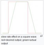
My 2ct. The total amplifier distortion for a certain output power can be leading for a design. The reason for auditive evaluation is with the different forms of distortion, one more offending than the other. When gross distortions are kept in reason (think of blocking, inefficient biassing, IM) the more subtle distortions can be noticed. Slew rate distortion is one of those, arriving from a driver stage not up to its task or from a not compensated topology, as FB can be beneficial to SE design as well. On peaks one should consider slew rate limitation, that's why a larger drive is necessary. The general consideration is that 2pifVPK can be fulfilled at max output, to be tested with a 10KHz square wave.
Attachments
Headroom is a term associated with studio equipment where microphones can overload the pre amplifier (for instance). It describes the possible limit before onset of gross distortion above the average level. I don't see use of this term in power amplifier design unless someone gives an explication of its merits.
- Home
- Amplifiers
- Tubes / Valves
- Gain vs. Headroom