Hello, I have an SAZ 1500 in front of me I bought as an experiment to see if I could fix it. I have a little tech background, but this is my first time in a 12v amp. I bought this amp, replaced all the output mosfets, and immediately blew all four 40amp fuses, as well as some of the new mosfets. I removed all the output mosfets, and used a bench supply to turn it on, but the supply would go into protect and not feed any more than 8 volts. While poking around the unit, something labeled DK QK (looks like a transistor?) on the daughter card smoked. I am curious if anyone could explain to me what this card actually is, it's function, and if this burnt transistor could have caused the previous issue as well as its own demise. Should I just replace the DWM1216FV or is there something else that could have cause this and the rest to fail?
Attachments

Hello,nice to meet another starter. Better make a Photo from the whole board.
The card with the burned Transistors is the driver card for the mosfets. Make a good Picture from both sides. This card has to be repaired, before you can mount new mosfets.
The card with the burned Transistors is the driver card for the mosfets. Make a good Picture from both sides. This card has to be repaired, before you can mount new mosfets.
In the future, use a single 10 or 20 amp fuse to offer greater protection to the FETs. Also have all FETs clamped to the heatsink when powering the amp up to prevent them from overheating (which can happen within seconds).
If you're new to repair work, I'd suggest that you read the basic amp repair page (link in sig file below).
The 470 ohm resistors near the driver transistors that failed, commonly go out of tolerance and must be replaced.
If you're new to repair work, I'd suggest that you read the basic amp repair page (link in sig file below).
The 470 ohm resistors near the driver transistors that failed, commonly go out of tolerance and must be replaced.
In the future, use a single 10 or 20 amp fuse to offer greater protection to the FETs. Also have all FETs clamped to the heatsink when powering the amp up to prevent them from overheating (which can happen within seconds).
Thanks, I will only be using one fuse in the future until I ***** the problem. When they blew, the amp was fully assembled with all fets clamped down. I have since powered it up a few times on a current limiting supply (under 3 amps) without the heatsinks. I will make sure to measure the fets again before any more work.
If you're new to repair work, I'd suggest that you read the basic amp repair page (link in sig file below).
I am familiar with your site, I found it many years ago (Through Realm of Excursion maybe?) and rediscovered it today. I will be reading it again now that I am slightly more informed than I was at the time. Let me take the opportunity to thank you for assembling such a wealth of free knowledge.
The 470 ohm resistors near the driver transistors that failed, commonly go out of tolerance and must be replaced.
Are you referring to resistor located on this card or on the main board? Would you or anyone happen to have schematics that may help me make heads or tails of this board or card?
Hello,nice to meet another starter. Better make a Photo from the whole board.
The card with the burned Transistors is the driver card for the mosfets. Make a good Picture from both sides. This card has to be repaired, before you can mount new mosfets.
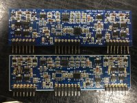
Hello, and thank you. Here is a photo of the amp. I was told by Sundown that they could sell me a replacement card, but not supply me with component data or schematics, so I may just purchase the card from them and see where it gets me, I am just reluctant to replace it without knowing why it burned up in the first place, was it due to another failure on the card or is there some menace on the board that could be lurking waiting to fry the next card I solder in?
Attachments

Q7, 11, 19 and 22 commonly fail and cause various problems. The 470 ohm resistors are the ones between those transistors and the larger driver transistors. All of this is on the driver board.
Thank you for all the advice so far. Sundown just contacted me and told me that they are three months out from restocking these driver cards, so it looks like I will have to try my hand at repairing this one, unless someone has a card to sell me here.
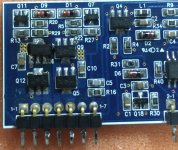
Q7, 11, 19, 22 all measure fine using the diode test as well as all the rest of the transistors on the card. However I have a fried Q6, which got so hot it melted some of the solder and slid out of place. You can see the burn mess it is currently in the photo. R27 also measures as a short, and I have some strange discrepancies between the brown caps between the left and right side. C7 is sitting at 1500Ω and C10 is at 150Ω. Neither of them charge or discharge.
Could anyone please identify what Q5 and Q6 are, they are both labeled DK QK and I have tried to google them a few times without success.
So could anyone provide me with values of the following?
Q6
C7
C10
Attachments
Transistor marked DK - 2sc4672
I'd suggest replacing 7, 11. 19 and 22. They run hot and have a high failure rate.
I think someone posted the value of C10 as a 0.1uf. It won't show as charging/discharging with most meters.
I'd suggest replacing 7, 11. 19 and 22. They run hot and have a high failure rate.
I think someone posted the value of C10 as a 0.1uf. It won't show as charging/discharging with most meters.
Okay, I found another driver card on eBay that was unused and decided I would be better off just replacing the card than trying to figure out these components. While I was at it, I ordered a 30V 10A supply. I put the card in it and powered up the supply and immediately popped the two mosfets I had installed in the output just to see if it was working. With all the output mosfets removed, I am now measuring 78v across the gate and source of the positive and -78v across the same legs of the negative.
I first thought that I would be looking at a DC signal from the modulation section causing the mosfets to lock on in full throttle. But that would maybe explain one side, but not them both staying on. Any suggestions on what I should look for, or am I thinking about this wrong?
I first thought that I would be looking at a DC signal from the modulation section causing the mosfets to lock on in full throttle. But that would maybe explain one side, but not them both staying on. Any suggestions on what I should look for, or am I thinking about this wrong?
The 30v/10a supply isn't what you need for amp repair.
I think you mean that you're reading ±78v on those pins/pads. If you read 78v 'across', you would have a difference of 78v between gate and source.
I think you mean that you're reading ±78v on those pins/pads. If you read 78v 'across', you would have a difference of 78v between gate and source.
The 30v/10a supply isn't what you need for amp repair.
I think you mean that you're reading ±78v on those pins/pads. If you read 78v 'across', you would have a difference of 78v between gate and source.
It's a variable supply, I had it on 14.5V, what would you recommend?
And yes, ±78v across those pads referencing ground. Would this indicate that the modulation circuit is bad?
'Across' would mean black probe on the source and the red probe on the gate.
I don't know what your budget for a supply is.
I don't know what your budget for a supply is.
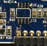
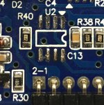
So I had bought another driver board and put it in the amp, still having lots of trouble. I eventually pulled the driver card after not seeing any nice square waves from it. I compared it with the one I originally pulled out and found that pins 5 and 6 of U2 of the new one are continuous with pin 2-4 on the card. I do not have this connection on the original one. I decided to repopulate the original, but I would like to test it out of the board because putting this in and out of the motherboard many times is starting to fatigue the vias. Does anyone have a test procedure for the driver card out of the amp?
Attachments
The class D - type 8 page has a lot of helpful information. If your browser doesn't show all of the images, right-click the link in the directory and open in new tab.
There is virtually no way to get the boards in and out of the main board without damaging the vias unless all of the pins are PERFECTLY straight.
Tech Tips 10, item 4 my be helpful for troubleshooting.
TT5, item 20 will help you get the driver boards out with less chance of damaging the vias.
Pins 5 and 6 of the TL072 aren't used. They're tied to ground. This is OK.
Thank you, I will look into all of these. I am having trouble with the images and the flash, so I will try that right click fix, thanks.
This amp is kicking my ***. I am now getting 50V DC on the speaker outputs and then the protect comes on and the amp completely shuts down so I can't poke around. I have replaced the TL072, and the LM211. I have checked all the transistors, diodes, and resistors on the driver board. None of the brand new 640/9640 are measuring a short. All gate resistors are the same for all banks. None of the 220 regulators for the driver card measure as shorts. All components are from Digikey.
Am I correct in assuming the issue is still the driver board? Like it is just turning on one side of the output and not oscillating?
Also, Perry, I am not seeing any of the flash or videos. Im on a Mac and I had to try several different archival programs to open the tutorial, as well as different browsers, no joy.
Try right-clicking the link for the page in the directory and opening the page in a new tab. Does that help?
At this point, I'd suggest removing the rectifiers to see if the amp will stay powered up and allow the drive signals to pass to the outputs.
At this point, I'd suggest removing the rectifiers to see if the amp will stay powered up and allow the drive signals to pass to the outputs.
Try right-clicking the link for the page in the directory and opening the page in a new tab. Does that help?
At this point, I'd suggest removing the rectifiers to see if the amp will stay powered up and allow the drive signals to pass to the outputs.
- Home
- General Interest
- Car Audio
- Sundown SAZ 1500 - DWM1216FV