
Hi
Im looking for some advice regarding an amp I´m planning to build. I have started to gather the components and at this point I´m looking for the coupling caps, 2uf 400V. They seem hard to find and the value 2uf is higher than what I´m used to. In amp´s I´ve built earlier the value is usually 0.22uf or 0,33uf.
So, my question is; is the value in the schematic 2uf right and if so where can I find a coupling cap with this value?
Any suggestions are helpful.
Cheers!
Last edited:
From Jantzen Audio you can get these (1.8uF or 2.2uF):
Silver Z-Cap - Jantzen-audio.com
I don't think it matters if it is exactly 2.0 or 2.2 uF.
....they are good value for the money.
Mundorf also makes coupling caps. in the same values......several "qualities"....
Silver Z-Cap - Jantzen-audio.com
I don't think it matters if it is exactly 2.0 or 2.2 uF.
....they are good value for the money.
Mundorf also makes coupling caps. in the same values......several "qualities"....
Hey! Thanks MEPER, I will look them up.
As you probably can notice, I´m not a techie, athough I have built 5 amps earlier with great (MO) results. I´m a bit curios about the coupling cap´s and the values. What could one expect in sonic difference if the 2uf was subed for say a 0,22uf or 4uf?
Cheers!
As you probably can notice, I´m not a techie, athough I have built 5 amps earlier with great (MO) results. I´m a bit curios about the coupling cap´s and the values. What could one expect in sonic difference if the 2uf was subed for say a 0,22uf or 4uf?
Cheers!
The cap size wil affect the frequency response. If it is too small it will cut the low frequencies. It it is too big in value the physical size is large and it is more expensive and it may not be that good to transfer the very high frequencies. Apart from that a more experienced "tube guy" than me may tell you some more.......
The cap I linked to is where price and quality is a good match. You can get much more expensive caps if you want. E.g. Audio Note silver foil caps.
Silver Foil Capacitors | Hifi Collective
https://hfc-fs.s3-eu-west-1.amazonaws.com/s3fs-public/audionote_silver_price.pdf
....if you look at the prices you don't want a cap with a higher value than necessary?
Silver Foil Capacitors | Hifi Collective
https://hfc-fs.s3-eu-west-1.amazonaws.com/s3fs-public/audionote_silver_price.pdf
....if you look at the prices you don't want a cap with a higher value than necessary?
The Vgk of the second half of the 12AX7 is shown as -15V (152V - 137V = 15V), this is incorrect as the 12AX7 would not conduct at this Vgk. As it is an SRPP stage (oddly drawn) and both cathode resistors are effectively 1k and the bottom Vgk = -0.92V then the top must be the same Vgk of -0.92V
The Vgk of the second half of the 12AX7 is shown as -15V (152V - 137V = 15V), this is incorrect as the 12AX7 would not conduct at this Vgk. As it is an SRPP stage (oddly drawn) and both cathode resistors are effectively 1k and the bottom Vgk = -0.92V then the top must be the same Vgk of -0.92V
Hi Ejam
I found the schematic at T.Kanoh´s page and he seems to have designed a couple of amps in the past, are you sure? Vacuum Tube Amplifier / EL156 SingleEnded
Ok, anyway, this is almost over my knowledge. If this is as you say do you have any suggestion of what to do to get the same voltage at both locations?
Any suggestion is helpful, thanks.
Last edited:
EL156 is a rare tube. When found is expensive.
Yes, FullRangerMan, they are expensive same as NOS GEC KT88´s.......
Cheers
12AX7/ECC83 100k or more -plate impedance is a very poor driver and even worse with cathode follower following; I doubt you would get sufficient drive with a triode connected EL156; There must be much better circuits than this one
12AX7/ECC83 100k or more -plate impedance is a very poor driver and even worse with cathode follower following; I doubt you would get sufficient drive with a triode connected EL156; There must be much better circuits than this one
Hi Multi
You are welcome with suggestions, thank you.
Well he seems to have good results with his circuit if you check his web page: Vacuum Tube Amplifier / EL156 SingleEnded
Yes, FullRangerMan, they are expensive same as NOS GEC KT88´s.......
Cheers
I believe Shuguang still make them at about 60 EUR each.
The coupling capacitor is too large of a value at 2uF.
Perhaps the intent was to be able to drive large values of grid current into the output tube's control grid.
A 12AX7/ECC83 is not a good tube to drive grid current into an output tube's grid.
Even if the driver has sufficient grid current, the 2uF is going to charge up, and the bias to the output tube will shift, and take a very long time to recover. It will take 5 time constants to recover, and 1 time constant is R x C = 0.48 seconds, so that is 2.4 seconds to get back to proper bias.
The 240k Ohm grid resistor and 2 uF has a -3 dB low frequency cutoff at 0.33 Hz. Even the -1 dB response is at 0.66 Hz.
That is far below the frequency response of any output transformer and of any loudspeaker you are likely to use (and far below most recording signals too).
If the intent is to have large control grid current, then select a driver tube with a lot more current capability, and put an interstage transformer between the driver tube's output and the control grid of the output tube.
That will make for a much faster recovery time.
Last edited:
hoohbt
May be the designer wants/ likes very slow sound with out any dynamics?? Thats what you will get for sure!!!!
Be careful buying Chinese EL156; I bought 20 every one was a dud; returned them and got them matched the second lot were even worse. lots of shorts. Maybe if you buy from a Good big re-seller; will be OK.
Phil

Another observation about the Schematic:
The EL156 plate has 442V, and the screen has 438V. That is a 4V difference.
The plate to screen resistor is 100 Ohms.
4V/100 Ohms = 0.040 A (40mA).
438V at screen -23.3V at cathode = 414.7V screen to cathode.
414.7V x 0.04A = 16.59 Watts on the screen.
That is 2 times the 8 Watt maximum screen rating!
How long will you be able to listen to it?
Ok, thank you all for the input.
So thats a bummer, I guess I will have to find a different circuit that will work. Anyone know of a good SE EL156 and preferably integrated/stereo?
Cheers
So thats a bummer, I guess I will have to find a different circuit that will work. Anyone know of a good SE EL156 and preferably integrated/stereo?
Cheers
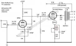

The 100R merely makes the triode connection, there is no issue with excessive screen grid dissipation.How long will you be able to listen to it?
Just go with the first schematic, and change the coupling capacitor to a smaller value if you can’t find a 2uF. With the 4.7k grid stopper, there shouldn’t be any issue with grid current.
Just go with the first schematic, and change the coupling capacitor to a smaller value if you can’t find a 2uF. With the 4.7k grid stopper, there shouldn’t be any issue with the grid current.
Thanks Jazbo8.
Im getting mixed messages about the first circuit from several members?? Im not a techie so I rely on others to guide me. Could someone please give me a straight answer if the first circuit is a no go or not. The circuit designer seems to be an experienced designer and has test results to show that it in fact works.
Thankful for any input, cheers.
- Home
- Amplifiers
- Tubes / Valves
- SE EL156 amp