Frequency is a very important parameter to assess the condition of a distribution grid on a global scale.
Unlike voltage variations that may only affect local sections of the network, frequency necessarily encompasses the whole of the network, because any local deviation leads to a linearly increasing phase-shift, until something breaks if uncorrected.
The exact frequency is heavily correlated to the instantaneous load, and the balance between production and demand, and is therefore an important health indicator.
https://en.wikipedia.org/wiki/Utility_frequency
This frequency can be measured with an ordinary frequency-meter, but a dedicated instrument is preferable because the jitter caused by various polluting signals should first be eliminated, and the frequency should be averaged on a sufficient number of periods in order to extract a stable value.
It is also preferable to display just the deviation, absolute or relative rather than the actual frequency, which can be cumbersome and leads to mental gymnastics.
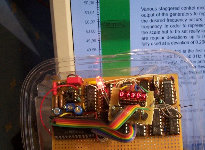
Here, I have chosen to display the absolute deviation in positive or negative: all the decimals above or below 50Hz.
In fact, this circuit is not actually a frequency-meter, not even a deviation frequency-meter in fact: what is actually measured is the period, which is converted to frequency, not with an inversion, but with just a mere change of sign.
How is it possible?
In everyday life, we assume that the 5% between 95% and 100% are identical to the 5% from 100% to 105%, but that's not stricly true: 1/0.95=1.05263, which means there is a 0.263% error.
This is certainly not negligible, but for a proportion much smaller than 5%, the error becomes vanishingly small.
In a 50Hz system, the maximum error is 0.1Hz, ie. 0.2%.
Here, the period deviation is extracted and then scaled and manipulated to look like a frequency when displayed.
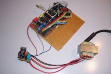
How it works
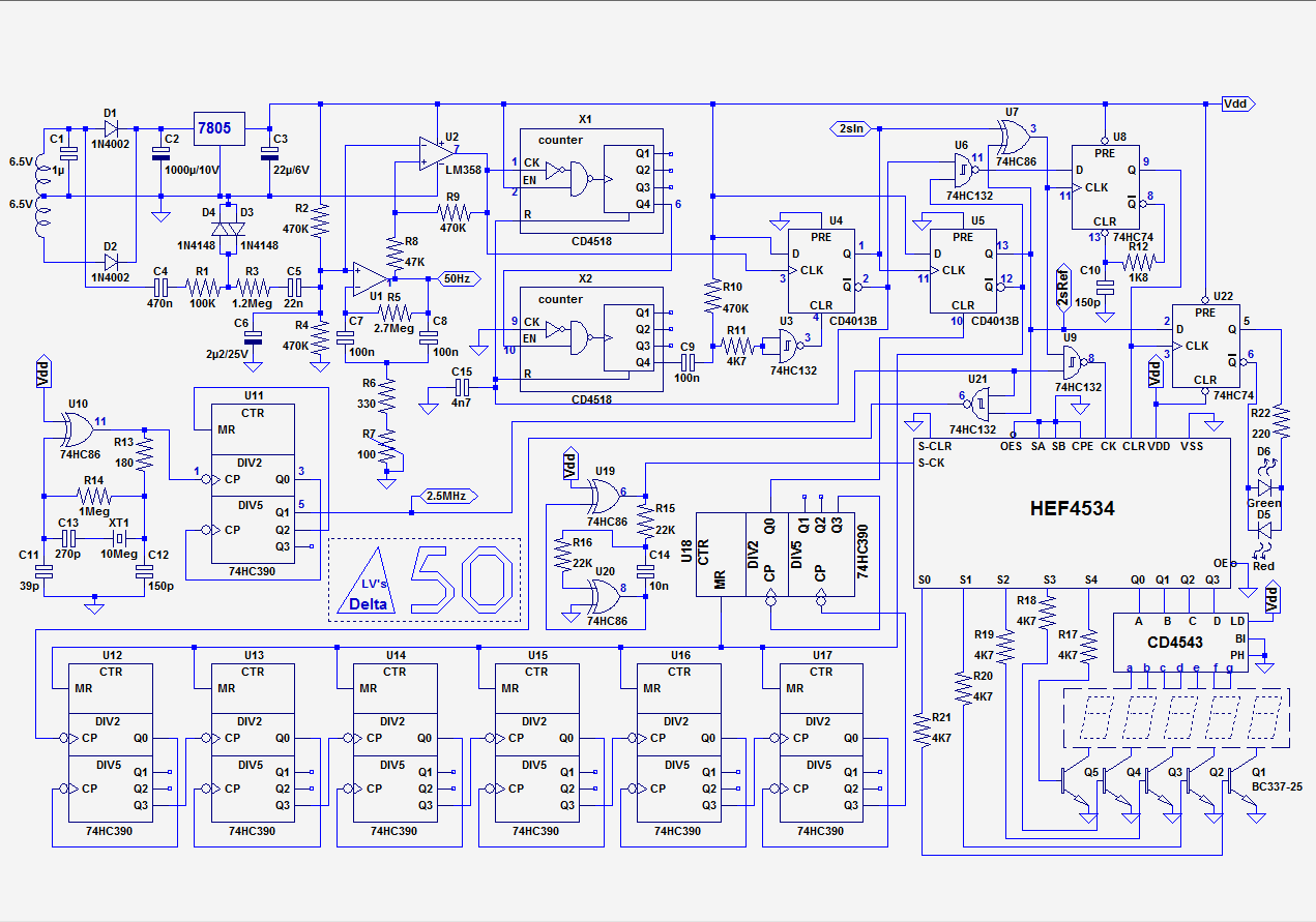
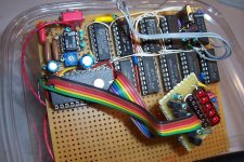
The 50Hz to be measured is first clipped and crudely filtered thanks to C4 to 6, D3, D4, R1, R3 and is applied to a high Q selective filter, U1.
The resulting signal is squared by U2 and applied to the logic.
This front-end happily accepts signals from 0.5V rms to 150V, even very polluted ones: a 60cm wire hanging from the prototype was able to collect a sufficient signal.
X1, 2 and U4 count 100 input pulses and generate a 2 second pulse.
This pulse is compared to a X-tal generated one, with a string of counters and U5 fed by a 2.5MHz reference.
This reference establishes the final resolution: 10E-5 Hz.
Initially, I had planned for a 4-digit instrument, because the range from 49.90001Hz to 50.09999Hz was sufficient, but the LSI counter and display I had in my stock were 5-digits, and it ended as a 5 digit.
The first digit will always read 0 (unless Vladimir and Donald decide to have some fun with Kim), but it doesn't matter, it is free: the HEF4534 is dirt-cheap anyway.
The two 2-second pulses are compared in U7, where the counting window is generated.
The 4534 is rather crude, and does not include latches, which means that the counters reset is made "on the fly", at the start of each counting period by U8 wired as a one-shot.
The counting is in real-time, and is not hidden, but it lasts a few ms at most, which means it appears as a barely visible flicker every 2s on the display.
U22 extracts the sign of the deviation.
The title indicates that this project is useless, because the data is obtainable from various sites (here for most of Europe):
Online-measurement of the mains frequency
It is fun and instructive though, and it can also show local, temporary swings that deviate from the global average, possibly indicating some local stress conditions.
The resolution is also finer: 10E-5Hz on 50Hz is 0.2ppm, and the update rate is quite fast at 0.5Hz.
The mix of input analog filtering + digital averaging on 100 periods provides good and reliable readings, even with this relatively fast rate.
Unlike voltage variations that may only affect local sections of the network, frequency necessarily encompasses the whole of the network, because any local deviation leads to a linearly increasing phase-shift, until something breaks if uncorrected.
The exact frequency is heavily correlated to the instantaneous load, and the balance between production and demand, and is therefore an important health indicator.
https://en.wikipedia.org/wiki/Utility_frequency
This frequency can be measured with an ordinary frequency-meter, but a dedicated instrument is preferable because the jitter caused by various polluting signals should first be eliminated, and the frequency should be averaged on a sufficient number of periods in order to extract a stable value.
It is also preferable to display just the deviation, absolute or relative rather than the actual frequency, which can be cumbersome and leads to mental gymnastics.
Here, I have chosen to display the absolute deviation in positive or negative: all the decimals above or below 50Hz.
In fact, this circuit is not actually a frequency-meter, not even a deviation frequency-meter in fact: what is actually measured is the period, which is converted to frequency, not with an inversion, but with just a mere change of sign.
How is it possible?
In everyday life, we assume that the 5% between 95% and 100% are identical to the 5% from 100% to 105%, but that's not stricly true: 1/0.95=1.05263, which means there is a 0.263% error.
This is certainly not negligible, but for a proportion much smaller than 5%, the error becomes vanishingly small.
In a 50Hz system, the maximum error is 0.1Hz, ie. 0.2%.
Here, the period deviation is extracted and then scaled and manipulated to look like a frequency when displayed.
How it works
The 50Hz to be measured is first clipped and crudely filtered thanks to C4 to 6, D3, D4, R1, R3 and is applied to a high Q selective filter, U1.
The resulting signal is squared by U2 and applied to the logic.
This front-end happily accepts signals from 0.5V rms to 150V, even very polluted ones: a 60cm wire hanging from the prototype was able to collect a sufficient signal.
X1, 2 and U4 count 100 input pulses and generate a 2 second pulse.
This pulse is compared to a X-tal generated one, with a string of counters and U5 fed by a 2.5MHz reference.
This reference establishes the final resolution: 10E-5 Hz.
Initially, I had planned for a 4-digit instrument, because the range from 49.90001Hz to 50.09999Hz was sufficient, but the LSI counter and display I had in my stock were 5-digits, and it ended as a 5 digit.
The first digit will always read 0 (unless Vladimir and Donald decide to have some fun with Kim), but it doesn't matter, it is free: the HEF4534 is dirt-cheap anyway.
The two 2-second pulses are compared in U7, where the counting window is generated.
The 4534 is rather crude, and does not include latches, which means that the counters reset is made "on the fly", at the start of each counting period by U8 wired as a one-shot.
The counting is in real-time, and is not hidden, but it lasts a few ms at most, which means it appears as a barely visible flicker every 2s on the display.
U22 extracts the sign of the deviation.
The title indicates that this project is useless, because the data is obtainable from various sites (here for most of Europe):
Online-measurement of the mains frequency
It is fun and instructive though, and it can also show local, temporary swings that deviate from the global average, possibly indicating some local stress conditions.
The resolution is also finer: 10E-5Hz on 50Hz is 0.2ppm, and the update rate is quite fast at 0.5Hz.
The mix of input analog filtering + digital averaging on 100 periods provides good and reliable readings, even with this relatively fast rate.
Attachments


Back around 1950, Columbia Missouri USA had its own power plant. There was an electric clock on the wall, a very fine watch in the Head Engineer's pocket. Once a day he compared them, and trimmed the steam-engine governor so the plant kept the same time as the watch.
One of the things that plant powered was university research into stability of large AC power grids. These were in wide use in the eastern states (from around 1920 in the east Pennsylvania area) but stability was only generally understood. With ball-and-disk (later opamps) analog computers they could set up large virtual networks and disturb them without breaking the system.
By the 1970s (and even now) there were three power grids in the US: East, West, and Texas. There were also large interconnects with Canada, as we know from one blackout which propagated many hundreds of miles around the Great Lakes and into NYC.
From pocket watches to phase/direction meters to computer monitoring and dispatching.
> data is obtainable from various sites (here for most of Europe):
Cute! I do _not_ know where to get that data for the US.
My reading is that the major deviation is power-contracts in 15 minute periods. They cut in a generator to take the expected load curve, initially there is an over-supply, and it takes some little time to re-balance the load and head back to sync frequency.
FWIW: My Fluke meter never deviates from 59.9Hz. (I am sure our long-term average is 60.000Hz on some fancy pocket-watch; the Fluke just does not aim for such accuracy.)
> swings that deviate from the global average, possibly indicating some local stress conditions.
My suspicion is, while "the grid" can agree to lag a little over a peak demand, as you say "deviation leads to .... something breaks". And that with modern dispatching, the grid can go from OK to dead faster than you will notice the change.
Elegant logic!
I would suggest that a line-locked recordplayer, with strobe stripes, but a crystal-sourced strobe light, would give some of the same information. But not as directly and not small enough for a sandwich tray.
What I think would be interesting is to log the data, in the off chance that a generation/distribution fault occurs.
We have an interesting political boxing match going on in oz with large scale renewable, and whether it is affecting price and reliability of power. One aspect is the protection settings wrt frequency change that in the past were mainly referenced to the inertial time-constants of electromechanical generators. Recent large-scale connections of renewable, and decommissioning of thermal generation has significantly modified the frequency change characteristics when distribution faults and generator/link disconnections occur.
But perhaps Elvee your detection mechanism includes too much smoothing to capture interesting data when a grid blackout occurs.
> data is obtainable from various sites (here for most of Europe):
Cute! I do _not_ know where to get that data for the US
Here are some other online monitors:
Dynamic Demand
Mains Frequency - European Power Grid
https://www.swissgrid.ch/swissgrid/en/home/experts/topics/frequency.html
G. B. National Grid status
I don't find something similar for 60Hz, but it probably exists
It would give phase information, which is similar except for the integrationI would suggest that a line-locked recordplayer, with strobe stripes, but a crystal-sourced strobe light, would give some of the same information.
There are probably such projects around, most likely based on Arduino, RasPi or similarWhat I think would be interesting is to log the data, in the off chance that a generation/distribution fault occurs.
Here, the average response time is ~1.25s, 2.5s worst case, but for much larger excursions than 10E-5Hz, the filtering and averaging could be eased by a factor 10, leading to a maximum response time of 0.25sBut perhaps Elvee your detection mechanism includes too much smoothing to capture interesting data when a grid blackout occurs.
When I said that this project is useless, it is probably an exaggeration: from my POV, it is useless, but let's not generalize too quickly: if an off-grid local network needs accurate monitoring for some reason, it could certainly be useful.
Even in the perspective of a global grid, it could also (in theory) be useful: if a temporary deviation with respect to the global, averaged value is noted, it means that some stress exists between the local nodes and the grid, but detecting such a rare and fugitive occurrence would mean looking permanently at the display and a PC screen to detect any discrepancy.... Not very appealing, unless it is automated in some way.
There could be other uses: for example, to monitor the speed deviation of a turntable or anything else: just fit some kind of sensor, a frequency divider if required, and you can very precisely detect speed deviations of about anything.
Note that the frequencies and dividers can be tailored to handle any format or base frequencies: for example, a relative (%) rather than absolute (Hz) deviation could be displayed.
You could have stuffed the entire digital circuit into a small FPGA. You can get hobbyist or student versions of Xilinx and Altera tools for free.
Sure. How much does a basic FPGA cost, how much costs the devboard, does the part have a TTH version?
All questions important to DIYers
All questions important to DIYers
Sure. How much does a basic FPGA cost, how much costs the devboard, does the part have a TTH version?
All questions important to DIYers
A part with more than enough gates for your circuit is about $5-7 from Digikey.
You can get wire wrap PLCC sockets or solder point to point.
The basic Altera and Xilinx software is free.
Third party programming pods are available cheap all over the net and you can even build your own. The premium Altera and Xilinx pods are of course over $100.
Even if it costs more than a handful of TTL/CMOS chips, consider this.
1) You make wiring changes with a mouse rather than a soldering iron or wrap tool.
2) The free software has basic timing simulation built in.
3) You can do simple schematic entry and there is a library of all the standard TTL chips. For example if you want a 7474 flip/flop, there is a model already built. You don't have to build it out of basic gates although you can if you want.
4) If and when ready you can also use HDL languages to design logic circuits.
5) The modern FPGA's are NVRAM based. You can erase them and use them for another project up to at least 100 cycles.
I too am a 1970s era guy that started out with TTL chips. But once you try FPGA's, you won't look back. It like comparing a drafting board to a CAD program.
Last edited:
For someone having already invested time, resources and energy into a system, it certainly makes sense to get the most of that investment.
Something I don't like and prefer to avoid is getting "married" to a single source, perhaps two.
Whenever possible, I choose commodity components
Something I don't like and prefer to avoid is getting "married" to a single source, perhaps two.
Whenever possible, I choose commodity components
- Status
- Not open for further replies.
- Home
- Design & Build
- Equipment & Tools
- Useless yet fun: a mains frequency deviation-meter