Hi
I've an old Audio Innovations Series 500 that seems to have gone wrong. I've replaced the four EL84s and three ECC83s and am waiting to get my hands on a pair of ecc88s to complete the valve upgrade programme.
However, I was surprised to find that replacing the 84s had no effect as I'd previously thought that they were shot. I'm wondering if there is some other failed component inside it. I have the schematics but I'm not very experienced with tube amps - just love the sound - and would like to ask if there's anything in particular I should check first. I read somewhere that a particular capacitor goes and that leads to tube failure but cannot remember the details..
Symptoms are as follows:
I guess the first thing would be to test the output from the tape loop. This will provide some indicator for the phono stage.
Can anyone suggest the sorts of things I should look for? What typically fails in these amps? I can post the schematics if it would help.
Thanks
JonB
I've an old Audio Innovations Series 500 that seems to have gone wrong. I've replaced the four EL84s and three ECC83s and am waiting to get my hands on a pair of ecc88s to complete the valve upgrade programme.
However, I was surprised to find that replacing the 84s had no effect as I'd previously thought that they were shot. I'm wondering if there is some other failed component inside it. I have the schematics but I'm not very experienced with tube amps - just love the sound - and would like to ask if there's anything in particular I should check first. I read somewhere that a particular capacitor goes and that leads to tube failure but cannot remember the details..
Symptoms are as follows:
Humming (well it's allways done that a little bit, I guess there is a bad earth in there somewhere).
Very very low output which distorts if you turn the volume up all the way, but stays quiet.
Phono stage is dead quiet, no output at all.
I guess the first thing would be to test the output from the tape loop. This will provide some indicator for the phono stage.
Can anyone suggest the sorts of things I should look for? What typically fails in these amps? I can post the schematics if it would help.
Thanks
JonB
If the company is out of business and there's no copyright issues, the schematics would help immensely.
The electrolytic capacitors, especially those at the cathode of the 84's are shurely bad.
This is due to the high operating temp.
Dick
This is due to the high operating temp.
Dick
If the company is out of business and there's no copyright issues, the schematics would help immensely.
Schematics can be found here .
More links:
Dimitri's website More information on the AI500
Classic 25 homepage Basicaly the kit version of the AI500, with information on modding.
BTW: my AI500 uses el34's, not the el84's.
Good luck!
AI 500 integrated
There is nothing wrong with your AI 500.
You are just using the wrong type of output tubes, you need EL34's there and not EL84's.
You can get 2 matched pairs of Svetlana EL34's from PMComponents at a reasonable price.
Maybe it would be a good idea to get 3 of those new Svetlana 12AX7's as well (a rumour is spreading around about these tubes) and a new pair of ECC88's.
This is a fine amp and if the 25 watts per channel are enough for you then go on and,
1) replace all electrolytic caps with new high quality ones (esp. the 100uf/100v one between the output tube cathodes to earth in parallel with the 220R resistor),
2) get rid of the cheap selector switches and pots (shop around for ELMA and ALPS, the amp is worth it),
3) check the tube sockets for play and wear replacing them with high quality ceramic ones.
If you cannot perform these tasks yourself, give a call to Mr. Peter Qvortrup of Audio Note UK. He is the man behind Audio Innovations and maybe he will be able to help you servicing the amp.
Good luck,
Nick
😉
EL84s? Ooops...
Nick
Sorry about that, it was a typo. I do have a matched quad of Svetlana EL34s in there and the ecc83s are (matched) Sovtek 12AX7LPS. Actually, I've got a spare one as I bought a matched quad of them. I'm bidding on a set of ecc88s right now on eBay to complete the valve replacements.
You're right, it's a bloody marvellous sounding amp and that is why I bought it all those years ago. However this particular one has a very chequered past as it was reputedly torched in a factory fire (looks like soot but no heat damage) and has been worked on by some questionable individual who has attempted to put DIY shielding inside it (bent bits of tobacco tins IIRC). It only cost £300 at the time! However, it has worked fine for many years and only got stored away when something even better came along. But I want to resurrect it now for my study, so I'm going to have a go at it.
Thanks for the replies and any other advice would be much appreciated. I don't like the look of some of those voltages alluded to on the power supply schematic... so "proceed with care" is the order of the day for me!
JonB
Getting access...?
Is it just me or is the bottom plate the only access to the internals of the AI500?Since everything is mounted directly on the top covwer I would expect to be able to lift it off or hinge it back. Well, I can see the allen bolts as well as anyone but is it an adviseable thing to do? Or does all work take place from the underside?
Is it just me or is the bottom plate the only access to the internals of the AI500?Since everything is mounted directly on the top covwer I would expect to be able to lift it off or hinge it back. Well, I can see the allen bolts as well as anyone but is it an adviseable thing to do? Or does all work take place from the underside?
right, I'm in there.
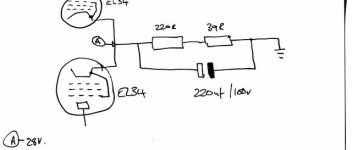
The circuit off the cathodes on both sides of the amp have been changed relative to the schematics. I've attached a diagram and described it:
Cathodes of both 34s are joined as per normal.
This goes into two resistors (connected in parallel, ceramic, wire wound) with a measured resistance of 220R.
On the other side of this is the fuse resistor, again a wire wound ceramic component. Its value is 39R (as opposed to 15R which I was expecting).
The capacitor is a 220/100 which I assume means "220 uF / 100 V" and it bridges the resistors, all of them, including the 39R "fuse".
The -ve end of the cap is earthed as you'd expect, but the +ve end is connected to the cathodes.
The fuse resistors and 220R pairs are all working (insofar as the meter confirms their expected values).
However, bridging all resistors with the capacitor doesn't look like a very good idea to me.
On the schematic is a measurement point "R" which states the voltage at the cathodes should be 28V. A quick check with the meter confirms that that is the case.
How can I test the capacitor in-circuit? It doesn't show signs of burnout.
Regards
JonB
Attachments
Jon
yes....useall all service on the series 500 is made from the buttom only, you only lift the hinge at the rear if the tranformers or main capacitors have failed
I dont regard your 500's sickness as any greater prob, just the useall maintaince ...actully i have salvage a lot of AI 500/800's of which a few literally went on fire (lol)
Send a mail where to mail all the info you need 😉
I can't send a mail to you throught the bulletin board as your user preferences seem to indicate that you don't want to receive mail from it.
Errm. I would rather not publish my eMail address because some spam bot will harvest it from the site and I'll be innundated! I don't need any Gener1c \/1agra thank you very much... 😉
Tell you what, I'll spell it phonetically. dr underscore zee at en tee ell wurld dott comm
There you are - you can work it out but a spam bot (probably) cannot.
PMik: being a ai500 owner too, I would really like to have a copy of your 'info' if possible. If you can't post it here, you can email me trough this board. Thanks!Ill send guide/explanation inc. pictures...asap.
ok, np
im almost finished creating the guide.
mail will be send for you tomorrow, course i got other things to attend for this evening 😉
Cheers 🙂
im almost finished creating the guide.
mail will be send for you tomorrow, course i got other things to attend for this evening 😉
Cheers 🙂
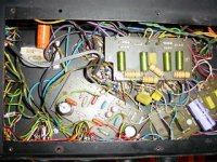
It's a rat's nest in there!!
I found a link here which has some photos of the Series 500. One of them is an interior shot and mine only has a passing resemblance to it. The main difference is that, whilst the photo on that site has really neat innards, mine looks like a mad professor has been trying to make a time machine out of it. It took me ages to locate the cathode capacitor circuit. How on earth can I sort out the rest of it? Even the three circuit boards, which look simple enough, have been modified. There's cut tracks, piggy-backed components, wires patched everywhere that look for all the world like the kind of lousy stuff you find in telephone circuits and I cannot quite see how it equates to the schematics. Some of the components are tightly wired to the valve holders - especially where the phono cable comes in. I can't even read the values on some of this stuff.
However, I'l start with an easy question : what are these three boards for? Do they have specific functions or are they just convenient holders for the components.
Argh! This thing is doing my head in...😕 But I know it is worth it because it used to work and sounded fabulous. Oh, and it's got the 16 ohm output transformer taps which - so I read - means the transformers are good quality.
Correction...
http://audio-innovations.nl.eu.org/gallery/thumbnails/TNai500-24.JPG
This is the photo I was talking about before (sorry about the broken llink) .
http://audio-innovations.nl.eu.org/gallery/thumbnails/TNai500-24.JPG
This is the photo I was talking about before (sorry about the broken llink) .
The big board at 6:00 is the power supply. The other two boards are the preamp and the driver circuits- I can't tell which is which.
Eh..?
Sy,
There's one at 12:00, one at 8:00 and one at 4:00 and they're all the same size.
Am I missing something?
My guess is you mean the one at 12:00 with the great fat resistors (ie, high wattage) on it..?
Sy,
There's one at 12:00, one at 8:00 and one at 4:00 and they're all the same size.
Am I missing something?
My guess is you mean the one at 12:00 with the great fat resistors (ie, high wattage) on it..?
The phono stage...
.. is the bottom left board.
I think the board top centre is part of the phase splitting circuit - it's connected to the ecc88s and each of the grids of the el34s (well, G1 anyway)
Therefore the bottom right board must be to do with power.
Hmmm.
.. is the bottom left board.
I think the board top centre is part of the phase splitting circuit - it's connected to the ecc88s and each of the grids of the el34s (well, G1 anyway)
Therefore the bottom right board must be to do with power.
Hmmm.
- Home
- Amplifiers
- Tubes / Valves
- Audio Innovations Series 500 problems