Mlloyd,
A folded cascode models as a single stage and is pretty fast. The disadvantage is the it has no current gain to speak of. It is a great topology if used correctly.
Regards,
Jam
A folded cascode models as a single stage and is pretty fast. The disadvantage is the it has no current gain to speak of. It is a great topology if used correctly.
Regards,
Jam
Re: I know of a few more...........
Jocko:
You're right, the Rowlands I was thinking about were the old beefy butt products from years gone back, not the girly man amps, I mean chip amps. 🙂
One of the things I miss most about the old rag "Audio" magazine was the schematic discussions to see who's thinking about or doing what and spending time trying to figure out why they would do it that way.
Then, talk to the designers during CES (back when they used to have them in Chicago) to see if I got it right.
Ahh, the good old days ...
PS - it's in the mail.
really ...
Originally posted by Jocko Homo
Yep, the old ones.......
But he has gone one step further away..............but don't tell CH........sssshhhhhh.......!
(Inside joke.)
I just had to fix one of "the old ones" a few weeks ago. Too damn heavy to lift onto my bench. Or from the customer's house. Had to fix it there, on the floor. Lightning strike took out the control circuitry.
Jocko
mlloyd:
If you include what the Japanese commercial audio designers have been doing, a folded cascode is not a particularly uncommon topology. Quite a few Luxman designs, likewise from Marantz, same with Denon, some from JVC, Stax... I don't know if I am to be considered a member of the Japanese audio design community, but FWIW I've also used folded cascodes commercially.
Not many folded-cascode designs have been published in the Japanese DIY audio magazines, however. The better-known designers like Kaneda, Kubota, Yasui et. al haven't published any folded-cascode designs, AFAIK.
Regarding the pros and cons of folded cascodes, I've written quite a few related posts on this forum. Using the search engine with the terms "folded cascode" and user name jcarr, I get 21 hits. Poor utilization efficiency of the voltage rails is an obvious weak point of folded cascodes, unless you sandwich something like a current-mirror stage between the folded cascodes and the final outputs.
regards, jonathan carr
Ouroboros said:seems to give better performance. At least SPICE says so!
Which particular performance do you mean ?
The folded cascode is not great for low thd, but for speed...
Mike
Poor utilization efficiency of the voltage rails is an obvious weak point of folded cascodes
jcarr: could you please elaborate on that one. I think quite the opposite unless i have misunderstood your point.
🙂
The output voltage swing is limited to the reference voltage of the common base transistors. That's why the output stage of the circuit I posted needs some voltage gain.Lars Clausen said:
jcarr: could you please elaborate on that one. I think quite the opposite unless i have misunderstood your point.
🙂
Mr. Evil: aaaa ok, but that doesn't have to be a weaker point in SFC stages, than any other kind of amplifier stage. You can always use a lower Vref 😉
Lars: The output signal of the folded cascode stage cannot swing any more than the biasing voltage that is applied to the bases of the folded cascode devices. As regards voltage swing and power supply voltage utilization efficiency, the key voltage levels are those that bias the folded cascode devices, not those on the power supply rails. Put another way, the voltages that bias the folded cascodes should be subtracted from the power supply rails. You could reduce the biasing voltages, but this should be done while considering the behaviour of the current sources and sinks that feed and drain the folded cascode stage.
A folded cascode is not the appropriate topology if you want to design a rail-to-rail amplifier design. Of course, it is possible to circumvent this limitation - at the cost of extra circuitry. But rather than do this, it is probably better to use a different topology if maximum signal voltage swing from a given power supply voltage is an important design goal.
I touched on similar things here, along with other comments:
http://www.diyaudio.com/forums/showthread.php?postid=117260#post117260
Although at that time my discussion was on the basis of a non-complementary folded cascode.
More here:
http://www.diyaudio.com/forums/showthread.php?postid=159092#post159092
As I said before, try the search engine.
regards, jonathan carr
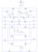
Here's an updated schematic. Q7/8 added as per Konrad's suggestion. With C2/3 they stop cross-conduction, although they do add about 10dB to each harmonic distortion component. I also swapped the zeners/current sources so they are *ahem* the right way around now.
Attachments
I am curious if anyone can pose sound theories as to why folded cascodes have not caught on in a bigger way among the "I make a living at it" audio design community (Nelson Pass and Jeff Rowland excluded, of course, there may be others?).
You must known this better than I do. Look at John Curl's JC3 power amp. What year is that? It uses folded cascode. He still uses that for Parasound amps.
McIntosh power amp also uses the same topology as JC uses there.
Charles Hansen submitted a cct here that uses folded cascode too.
Offcourse the famous one is X series (X1000, X650) passlab amps. NP even have patent on these.
Theory why? Maybe its because foldedcascode have low gain, while some designers insisted on using high gain and high feedback.
to LC
LC,
Why you likes non-feedback so much? Can you share your opinion on these vs feedback design?
LC,
Why you likes non-feedback so much? Can you share your opinion on these vs feedback design?
Incidentally, is the JC3 really a folded cascode? At least to me, a folded cascode is a topology in which there is _no_ gain going into the bases of the second-stage devices. Looking at the published schematics of the JC3, it looks like there _is_ some gain going into the bases of the second-stage devices. This is the same approach that I have seen for some early circuits by Accuphase, in that some of the output of the VAS was derived from the bases (per conventional VAS design), while the remaining part of the output came from the current injected into the emittors (cascode operation). It may be interesting to look at the ratio of how much the base contributes to the output and how much the emittors contribute to the output, and how the behaviour of the circuit changes (with and without global NFB). I seem to recall that Nelson may have mentioned some of this in Part 1 of his articles on the A75.
Lumanauw, you can get quite high gain from a folded cascode. Perhaps not 150dB, but certainly 90~100dB should be possible. The AD797 from Analog Devices, also a folded cascode, has around 120dB OL gain, if I am not mistaken.
regards, jonathan carr
Lumanauw, you can get quite high gain from a folded cascode. Perhaps not 150dB, but certainly 90~100dB should be possible. The AD797 from Analog Devices, also a folded cascode, has around 120dB OL gain, if I am not mistaken.
regards, jonathan carr
jcarr: Thankyou for expanding your views about the rail loss issue.
You are right this topology does not offer as low rail loss, as an integrated rail to rail op-amp.
However as i see it, the SFC does not suffer more from this problem than any other gain amplifier, that is usually found in audio equipment.
On the contrary! Why?
Well for the simple reason that when the output voltage is full positive, voltage over the emitter resistor of the positive gain transistor is constant or lower than at 0 signal.
In other (base driven) topologies, the voltage drop on the emtter resistor is (0,5 - 1 Volts) higher when the signal is full positive.
This adds to the rail loss in other designs. But not in the SFC.
That is actually why i chose the symmetric folded cascode for the N-Channel amplifier (posted in another thread). In that implementation the rail loss is only 0.8-0.9V transforming into the loss of output power from 200 to 196 Watts. (For a 200 Watts setup). Not a significant loss to pursue.
Finally after some thought i have come to the conclusion that it would be fairly simple to modify the folded cascode to have only like 100 mV of rail loss, by use of a few extra parts. Not so sure it benefit's the sound quality though.
Please comment 🙂
Hi !
Obviously i have no big problems with some voltageloss, otherwise
i wouldn't use tripledarlington. just for keeping all three transistors
idle i need 0.6v*3 = 1.8v. This increases a lot more with heavy load,
loosing ~1volt at emitterresistor, and having a vbe > 1v for output-bjt.
So i can live with loosing ~2volts (in my case) at the folded cascode.
With my other vas-designs i loose ~1volt. So if i use Vref of 1volt,
the FC has no disadvantage in this point...
I made some listeningtests to my prototype, i think it needs some
debugging. Sounds like i have a big 3rd harmonic somewhere, the
sound is definitely distorted, so i can't have any smooth or clean
sound. I didn't measure the output-bjts for this prototype, maybe
i have a big mismatch there ? This would explain why i have a load-
dependent DC-offset... (DC reduces when loaded with 4ohms instead
of 8ohms)
Mike
jcarr: In my judgement, the JC3 is only partly a folded cascode, since it is both emitter AND base coupled. (Feedback transistors are coupled to the bases of the gain transistors).
However it is a pretty nice little amplifier.
However it is a pretty nice little amplifier.
Lars: I'm not sure that I follow you. Allow me to set forth my pre-assumptions, as they may be different from yours.
I normally design folded cascodes with active current-source/sinks on the emittors, not resistors. I get better measurements and more preferable subjective listening results with the active current sources. One of the parameters that I consider when biasing the folded cascodes is how to obtain the most uniform behaviour from the active current sources/sinks under all possible conditions.
>Not so sure it benefit's the sound quality though.<
That's always the ultimate issue, isn't it? At the very least you wouldn't want anything that damaged the sound quality, even in the name of more ideal circuit behaviour.
>Please comment<
Rather than ask me for my opinion, just draw it up, build it, measure and listen! 😀
jonathan carr
Lars: Regarding the JC3 topology, you can add degenerator resistors to the sources/emittors of the input devices, and adjust these together with the collector/drain resistor values so that you can vary the voltage gain on the base of the VAS. My own experience is that no gain works and sounds the best, but OTOH, my experiences are my own and not necessarily relevant to anyone else.
regards, jonathan carr
regards, jonathan carr
- Status
- Not open for further replies.
- Home
- Amplifiers
- Solid State
- Symmetrical folded cascode.