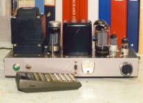
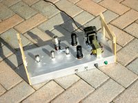
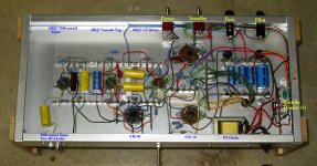
I built two of these in the early 60s. They were in constant use for more than 15 years until I bought a Sansui AU-717 / TU-717 Combo.
On the shelf for many years I replaced the coupling caps a few years ago. Both still operate OK.
That is an HP67 programmable in front from 1975. I used it this morning.🙂
On the shelf for many years I replaced the coupling caps a few years ago. Both still operate OK.
That is an HP67 programmable in front from 1975. I used it this morning.🙂
Attachments
Schematics
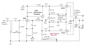
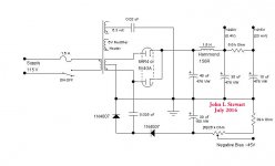
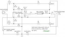
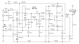
I've shewn the Bias & DC Balance Network separately for clarity. Notice there are no HT connexions as some designs use. The Bias & Balance cct was the subject of another published article.
I've shewn the Bias & DC Balance Network separately for clarity. Notice there are no HT connexions as some designs use. The Bias & Balance cct was the subject of another published article.
Attachments
Dear John,
I just read an application note of a 7199 that made me remember your thread: 7199:RCA Application Notes
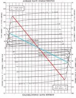
May I ask you if 25W is conservative? Drawing a loadline it seems that it hits g1=0 at around 110V and 220 mA, so more towards 35W.
Thank you.
I just read an application note of a 7199 that made me remember your thread: 7199:RCA Application Notes
May I ask you if 25W is conservative? Drawing a loadline it seems that it hits g1=0 at around 110V and 220 mA, so more towards 35W.
Thank you.
UL operation shortens the loadline. As a result the available power is reduced. So 100 % UL would be triode with its even shorter loadline. On the attached 6L6 plate family I have drawn the grid one zero bias curves for 20% UL, 43% UL & triode. The loadline is shorter than in pentode in each case. I did this several years ago, it needs to be cleaned up & presented better.🙂
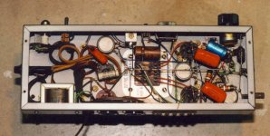
For the driver I used separate tubes, the paralleled sections of the 12AU7 form a better driver than the single triode section in the 6AN8 or 7100.
For the driver I used separate tubes, the paralleled sections of the 12AU7 form a better driver than the single triode section in the 6AN8 or 7100.
Attachments

Intriguing what you did with the 6AU6. I will have a second look tomorrow, after perhaps a few cups of coffee 😀
Thank you very much for your prompt reply John,
would you do it with SS devices, nowadays?
The only three places where Iì've seen that kind of feedback on g2 are:
- the 7199 application note;
- your amp;
- the Neve preamp.
would you do it with SS devices, nowadays?
The only three places where Iì've seen that kind of feedback on g2 are:
- the 7199 application note;
- your amp;
- the Neve preamp.
...The only three places where I've seen that kind of feedback on g2 are:.....
Radiotron handbook.
Attachments
Fascinating! I've tried this by inverting the secondary and driving the cathode, to good effect, but never the screen.
Both are driven in the #2 circuit, while being out of phase.
The return signal (coming over 220K) is in phase with the 6AU6 anode and gets "corrected" by the GNF signal from the secondary.
The return signal (coming over 220K) is in phase with the 6AU6 anode and gets "corrected" by the GNF signal from the secondary.
Yes, more ideally this requires no switching wires on the OPT secondary to make the phase correct.
May I ask you how you got the internal resistances of the tube at different percentages of feedback on screens? Thanks.On the attached 6L6 plate family I have drawn the grid one zero bias curves for 20% UL, 43% UL & triode.
Radiotron handbook.
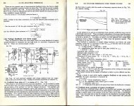
Altho the NFB is to the screen of the first tube it is not for the same reason. The circuit from HB3 is frequency selective to achieve a roll off in the audio range. A similar circuit using PP 807s does the same thing, attached here.
In the cct I used in the 1960 amplifiers the NFB is at DC & rolled off well below the audio range. Since it is NFB it stabilizes the operating point of the 6AU6 & 12AU7 as in a feedback pair. A couple of years ago I did a series of tests on this cct & compared it the the regular screen connexion. There was not much difference. The screen resister alone provides about 10 db of DC operating point stabilization. Think I put the results up on DIY, I'll pull that up later.
Attachments
May I ask you how you got the internal resistances of the tube at different percentages of feedback on screens? Thanks.
Those are the curves at zero grid bias, so not the rp that would apply at the operating point. The rp at the OP would be about twice these.
The curves are meant to establish one of the limits to the output voltage swing on the load, normally the OPT. I did that graphing many years ago, I'll have to dig thru my old notes. I used the G2 as variable taken from the 7027 curves, p5. The 7027 plate family is the same as the 6L6GC. The octal base connexions are slightly different. The G2 curves as the variable are very useful when they are available.🙂
There may be a minor error in the curves, was it PRR(?) who made the point that the FB is a fraction of the signal, not the HV PS.
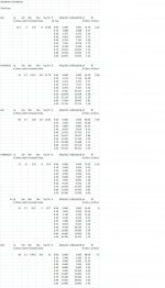
There was an article published in the 50s covering calculation of rps at various ULs, but the file is too large to post here. But I did a series of calcs based on the formulas in the article on a spread sheet a while back, see attached.
Winter coming here, much to do. So I'll be slow responding for a while yet.😱
Attachments
PP NFB to first stage Cascode Upper Grids
Here is a trick amp where internal NFB goes from the output plates to the first stage cascode diff amp. I'd seen something like this with NFB to the first stage PP pentodes. But pentode grids need current, this one doesn't. CFs drive the OP 6V6's so as an AB2 amp it can do 26 watts on a lab supply.
Here is a trick amp where internal NFB goes from the output plates to the first stage cascode diff amp. I'd seen something like this with NFB to the first stage PP pentodes. But pentode grids need current, this one doesn't. CFs drive the OP 6V6's so as an AB2 amp it can do 26 watts on a lab supply.
Attachments
Last edited:
Remarkable you get exact phase reversal with the 6bq7 input stages, as their 4bq7 load is active.
Articles on which rp was calculated
And the underside of that trick amp. All of my more recent amps have been experimental, not to look at or for sale. But the wiring needs to be done carefully to avoid problems.😀
The loadline has been corrected for AB2 operation.🙂
And the underside of that trick amp. All of my more recent amps have been experimental, not to look at or for sale. But the wiring needs to be done carefully to avoid problems.😀
The loadline has been corrected for AB2 operation.🙂
Attachments
-
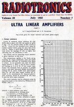 Calculation of Ultralinear Plate Resistance Radiotronics Magazine p1.jpg639.7 KB · Views: 118
 -
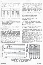 Calculation of Ultralinear Plate Resistance Radiotronics Magazine p2.jpg580.6 KB · Views: 73
 -
Amplifiers-and-Superlatives.pdf118 KB · Views: 76
-
 IMG_1383 Cascode Amp Bottom A 14W E Flash Labelled.jpg539.3 KB · Views: 103
 -
 6V6GTA 14W 4 PushPull C 7WB.jpg84 KB · Views: 102
Radiotron handbook.
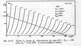
There is an error in the calculation of FB factor in that circuit example. The author neglected to take into account the resistance of the screen which is typically ~30k in voltage amplifier pentodes. So The 30K R1 is a parallel with the 30K screen resistance of the tube. Refer to the 6J7 G2 Curves, slope of the curve will indicate G2 resistance at that point.
This property is sometimes used to advantage to create a LF step in the freq response of a FB amplifier.🙂
I ran some tests a few years ago on I think a 6U8 & put the results on DIY. Find that later.😱
Attachments
Thank you very much! I've found that article: https://www.pearl-hifi.com/06_Lit_A...ol_01/Sec_02/081_Ultra-linear_Amps_w_Refs.pdfThere was an article published in the 50s covering calculation of rps at various ULs, but the file is too large to post here.
But on this forum there were rumors that it wasn't correct, and the ratio was linear with the impedance and not the voltage ratio of the ultralinear tap: Adjustable distributed load discussion
I've chosen 20% distributed load feedback on my EL84 BH based on Hafler and Keroes paper, but this new lockdown slowed down the already slow building of that amp.
Can it be this post with attachments? Gain stage with g2-feedback.I ran some tests a few years ago on I think a 6U8 & put the results on DIY. Find that later.😱
- Home
- Amplifiers
- Tubes / Valves
- Out of the Box: Part 6, a 25W PP UL 6L6GC Monoblock