Hi All,
I was considering replacing the 12BH7 pass tube in the regulator. If I do the math the circuit needs 402Vdc at 39.5ma. The 12BH7 has a 228v drop across it, so 9.006W. It's only rated for 3.5W each plate and both plates run in parallel. Most tubes do less than the single plate rating. So it appears that the 12BH7 is not up to the job. Did I miss something? They use a 6550/6H30 in the newer designs. I'm limited by the available heater current and 9 pin socket, so thinking of replacing it with a EL84 in triode? Sound correct? Not sure of the other changes required?
I was considering replacing the 12BH7 pass tube in the regulator. If I do the math the circuit needs 402Vdc at 39.5ma. The 12BH7 has a 228v drop across it, so 9.006W. It's only rated for 3.5W each plate and both plates run in parallel. Most tubes do less than the single plate rating. So it appears that the 12BH7 is not up to the job. Did I miss something? They use a 6550/6H30 in the newer designs. I'm limited by the available heater current and 9 pin socket, so thinking of replacing it with a EL84 in triode? Sound correct? Not sure of the other changes required?
Attachments
Should I post this in the "tubes" section? Someone told me this is a "buffer" style regulator...not sure what that means? I do see the two sections of the 12BH7 are doing different things?
I was considering replacing the 12BH7 pass tube in the regulator.
I wouldn't second guess ARC, they are careful in their equipment design.
The reason I ask, even they moved away from this design and are using 6550/6H30 in the newer reference designs.
This is an absolutely appropriate place.
Where did you come up with the current draw number?
Audio Research has made some inexplicable design choices over the years, and a lot of their products have poor reliability. There may or may not be a blunder in their circuit.
Where did you come up with the current draw number?
Audio Research has made some inexplicable design choices over the years, and a lot of their products have poor reliability. There may or may not be a blunder in their circuit.


Voltage drop measured at each plate or cathode resistor. Most of the resistors are 1 watt WW 1% and are still in spec. Current calculated and totaled. There are several opamps and transistors that all draw off of main B+, plus the 12BH7 and 12AX7 reg tubes themselves. Circuit running close to posted voltages on ARC schematic. I don't think 40 ma is out of line.
Do they run hot?
A lot of ARC products had failures because of insufficient air flow- I've repaired some of the old tube power amps where the circuit board just eventually started crumbling near the tube sockets. Lots of browning.
A lot of ARC products had failures because of insufficient air flow- I've repaired some of the old tube power amps where the circuit board just eventually started crumbling near the tube sockets. Lots of browning.
Yes. I was surprised how hot it was running, felt more like a power amp tube. I can see why people said they were replacing the 12BH7 every year or two. Top and bottom covers are perf metal. I was surprised they used this tube, even the SP10, which is a different design (bunch of 6DJ8s in the phono stage) runs two 6L6 in parallel.
OK, so a blunder. It happens. Problem with PCBs is that it's tough to rewire the socket to sub a higher dissipation tube. I'd strongly consider a solid state regulator.
While you're at it, replace the 1N4007 with UF4007. The little tantalum cap on the NE555 timer -- probably best switching it out for a new tantalum as they do fail.
The electrolytics are probably well past their "sell by" date and could be replaced.
The electrolytics are probably well past their "sell by" date and could be replaced.
I kind of want to keep it tube. The EL84 will fit the 9 pin socket and run on the available heater current. I do plan to replace the 1N4007 with UF5408 and the 24 volt circuit with UF4004 or schottky. I already did the all the filter caps. I didn't think to do the tantalum on the timer...thanks
I have a trusty Lambda Model 28 tube reg rated at 100ma that I plan to swap in to verify if the 12BH7 is just to wimpy. I do have a Salas sshv2 if I do a major change.
I kind of got the SP8 just to listen to, to see what all the fuss was about, so don't plan on big changes. I was just surprised with all the NFB used and power supply problems, but it is 35 year old technology.
First thing I did was to replace the 12BH7 with a NOS, and that made a difference. The PO said tubes had 500 hrs, I guessing more. I'm not a big fan of EH tubes, but I think the design demands are roasting them. I can see why people recommend replacement every two yrs.
I'm going to resurrect a dead thread. I have one of these that a friend brought over. He bought it "recapped and refurbished", but it had all the original 1981 electrolytics and some cooked PC board around the 555 timer. His complaint was that one day he turned it on and it made a pop and blew the fuse.
I dug in and found that the 400V rail was sitting at 75V, and tracked that down to a shorted C34 (1000pF styrene cap that probably didn't like the heat). I replaced that and the DC power supplies came up, except the 24V rail did not.
I loosened and retightened the hardware on the 24V TO-3 regulator, and that didn't help anything, so I put my bench supply on the output of the regulator and brough that section of the circuit up to 24V and only saw about 400mA of draw, so the regulator got cooked here too.
I continued debugging and found a blown zener feeding the 555 timer circuit, a blown 555, and LDRs that don't respond to changes in current. I fixed the 555 circuit and put an order in for LDRs, but the problem that I'm having is that if I leave the "low line voltage detector" parts in, pins 6/2 on the 555 never charge past about 1.5V. This is with the raw 37V supply and all the high voltage supplies running. I see 0V at all terminals on Q2 other than the collector, and I don't see any shorts on Q2, Q4, or Q5. I may just deactivate this circuitry so I can get this thing fixed and back into service, but I figured I would ask to see if anyone has any ideas on what to look for here.
Attachments
Broken SP-8
I’ll try to revive this thread but it seems that it’s gone stale. I got an SP-8 that behaves weirdly. It tries to reach the operating voltage, but can’t. I have to troubleshoot it from start…
I’ll try to revive this thread but it seems that it’s gone stale. I got an SP-8 that behaves weirdly. It tries to reach the operating voltage, but can’t. I have to troubleshoot it from start…
Thx. I’m just starting. When I measure the voltage at the fets between the first and third tubes, I can see voltage going up to about 120 and then dropping down to about 20. And it’s cycling like this about once a second. Something seems to be charging and then discharging. I think I should start by replacing all electrolytics, even though they check out fine on my cap meters. Schematics from different years call for different values for main caps, from 100uf to 200. Strange…
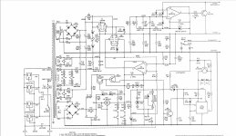
Replacing parts comes only after a tentative diagnosis. First, check each section of the supply
in turn, starting with the voltage on the Zener string, which should be 394VDC.
Next, check the output of the 12BH7A cathode follower, which should be 402VDC.
The symptoms that you observe are caused by the failure of the power supply to properly regulate.
The audio circuit is oscillating at a subsonic frequency (motorboating) because of this.
The large capacitors may or may not be related to this problem.
Last edited:
- Home
- Amplifiers
- Power Supplies
- ARC SP8 tube reg rebuild