Hello, I haven't posted here much but visit from time to time.
Previously I had re-caped a Parasound HCA-800ii and C/PT-600. I had found that about 1/3 of the electrolytic caps had gone out of spec. The signal path caps were replaced with Nichicon FG and KZ. The improvement was quite dramatic. The background is now very dark and imaging with my Polk LSi-15's is fantastic. I know that these are rather lowly components in the Parasound line but they are enough to make me a fan and I plan to move up the Parasound chain as I am able.
I recently picked up a Parasound HCA-1000a for very little $$ that needs a little help but still sounds good in spite. I was trying to hold out for a HCA-1200 or 1500 but couldn't pass this one for the price. There were things that bothered me about the HCA-800ii layout that seem to have all been addressed with the 1000a. The build is very beefy and I love the symmetry. I look forward to restoring it to glory even is it is also on the lower end of the line.
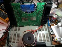
The amp looks to be in good shape except for some bad solder joints and the power supply caps are bulged. There are four Elna 10000uF, 63V. I saw mention of increasing to 15000uF, 80V, however, the ones that I have found look to be physically too large. It looks like I can go 35-40mm dia x 70mm high. Any recommendation for replacements?
As this amp has some age, what other items should I consider replacing?
The PCB is pretty dirty and seems to have a cruddy film (smoker environment). Is there anything I can safely use to clean the board or should I just leave it alone?
Thanks in advance
Stan
Previously I had re-caped a Parasound HCA-800ii and C/PT-600. I had found that about 1/3 of the electrolytic caps had gone out of spec. The signal path caps were replaced with Nichicon FG and KZ. The improvement was quite dramatic. The background is now very dark and imaging with my Polk LSi-15's is fantastic. I know that these are rather lowly components in the Parasound line but they are enough to make me a fan and I plan to move up the Parasound chain as I am able.
I recently picked up a Parasound HCA-1000a for very little $$ that needs a little help but still sounds good in spite. I was trying to hold out for a HCA-1200 or 1500 but couldn't pass this one for the price. There were things that bothered me about the HCA-800ii layout that seem to have all been addressed with the 1000a. The build is very beefy and I love the symmetry. I look forward to restoring it to glory even is it is also on the lower end of the line.
The amp looks to be in good shape except for some bad solder joints and the power supply caps are bulged. There are four Elna 10000uF, 63V. I saw mention of increasing to 15000uF, 80V, however, the ones that I have found look to be physically too large. It looks like I can go 35-40mm dia x 70mm high. Any recommendation for replacements?
As this amp has some age, what other items should I consider replacing?
The PCB is pretty dirty and seems to have a cruddy film (smoker environment). Is there anything I can safely use to clean the board or should I just leave it alone?
Thanks in advance
Stan
Is there anybody out there? I just thought I would benefit from the knowledge and experience of those who have worked on these amps before.
Where would be a reliable source for buying the Elna LAO caps?
Stan
Where would be a reliable source for buying the Elna LAO caps?
Stan
You can clean the pcb with a brush and isopropanol(isoprop.alcool).Be carefoul with mkt capacitors,when you clean.
Regards
Andreas
Regards
Andreas
The amp had been working well on the bench. I was able to set the biases and all was good. I decided to move it upstairs to my 2-ch system to give it a try and bad things happened. It developed a hum and now goes in and out of protect mode. One channel has a bias that jumps between 6V and -6V. Must be something loose, shorted or bad solder connections. I figure it is time to have some fun now and work it over.
I am planning to re-cap all the electrolytics in this amp. I do plan to upgrade the PS caps to 12,000uF 80V. Is there any reason to replace / upgrade the other type caps (PSC, PST, PMD MPT)?
Thanks
Stan
I am planning to re-cap all the electrolytics in this amp. I do plan to upgrade the PS caps to 12,000uF 80V. Is there any reason to replace / upgrade the other type caps (PSC, PST, PMD MPT)?
Thanks
Stan
Last edited:
Thank you for the advise. I at least need to replace the PS caps as they are bulging. My experience re-caping my HCA-800ii found about 1/3 of the electrolytic caps were out of spec for uF and who knows how many others for esr.
I appreciate any other advice.
Stan
I appreciate any other advice.
Stan
I got the new caps in last night but haven't reassembled the unit yet. I hope to do that tonight. I did find a couple damaged traces on the PCB that I repaired. Perhaps this is why it had an intermittent hum and other funnies.
For setting the bias, I had found some instructions a while back for the factory setting. However, I read somewhere that Mr. Curl had a more optimal bias setting a bit higher. Can someone clue me in?
Also, the schematic that Tony at Parasound sent to me shows only one trim-pot / channel. Mine has two / channel (TRV101, TRV102 and TRV201, TRV202). I am assuming that TRV101 and TRV 201 are for setting the bias voltage. What is the other (TRV102 and TRV202) used for?
Thanks
Stan
I set the stock 10mv across the .33 emitter to 17 mv. on mine.
The traces are extremely thin and will lift off the board without much effort.
The heat related components will need a bend or standoff before soldering back again for additional support.
The bulging tops of the PS caps appear to be bad but if you take a belt sander or file around the edges to remove them the cans themselves were all fine. Replaced them with 15k Versions anyway.
Regards
David
Be careful going your own way on bias. If you go to high it can go into thermal runaway.
Hope you sort it out.
Nick
Hope you sort it out.
Nick
I have used this amp as surround channels almost every night for almost a year without any problems.
I did replace the thermal pads at the same time
You can still place your hand on the sinks without issue. I believe it was around (guessing) 50c as I recall.
I did replace the thermal pads at the same time
You can still place your hand on the sinks without issue. I believe it was around (guessing) 50c as I recall.
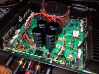
I got the caps swapped out, fixed a couple damaged traces on the PCB, got it back together and turned it on. I initially set the bias for 10mV. Later I found that the bias had dropped out on one channel. This was due to a broken solder joint on one of the emitter resistors and probably the source of the intermittent behavior. I pulled it apart again and went over the entire board. It seems that all the emitter resistor solder joints could easily be broken with a little wiggling if the resistor. All the connections were re-soldered and the amp was reassembled.
After a few hours run time, I adjusted the bias first to 17mV, checking the heatsink temperatures. Eventually, I set the bias to 20mV with the heatsinks running ~42deg C with the cover off. It is now running on my bench reproducing beautiful sine waves as I build confidence to place it in operation.
After a few hours run time, I adjusted the bias first to 17mV, checking the heatsink temperatures. Eventually, I set the bias to 20mV with the heatsinks running ~42deg C with the cover off. It is now running on my bench reproducing beautiful sine waves as I build confidence to place it in operation.
Attachments
Last night I used my old Denon DRA-835R for its preamp outputs, a Marantz CDR-615 as a source and played it out some "Dark Side of the Moon" through the HCA-1000a to some EPI M-50's. For Mr Curl's entry level amp, this thing sounds incredible. Even with this less than ideal setup, I hear details I never heard before without being harsh at all. The stage is spacious. Bravo John Curl! I look forward to moving up to your HCA-1500 but I'll enjoy this one for now. I cant wait to hook it up in my 2-ch rig with my Polk LSi15's.
There was one odd thing. The hum is gone but I had a buzzing that I thought might have been a ground loop issue since the Denon was across the room, plugged into a different circuit, and the long, cheap interconnect passed near a flourescent light. I started to run a chassis line to ground the units together and as soon as I loosened the hex key ground screw on the back of the Parasound, the buzzing went away. Tighten it and it comes back. I haven't investigated it yet. One of the level pots has a bent shaft so I am guessing it took a good hit to the rear. Perhaps something is loose.
There was one odd thing. The hum is gone but I had a buzzing that I thought might have been a ground loop issue since the Denon was across the room, plugged into a different circuit, and the long, cheap interconnect passed near a flourescent light. I started to run a chassis line to ground the units together and as soon as I loosened the hex key ground screw on the back of the Parasound, the buzzing went away. Tighten it and it comes back. I haven't investigated it yet. One of the level pots has a bent shaft so I am guessing it took a good hit to the rear. Perhaps something is loose.
Last edited:
Ok, so why would I have buzzing when the chassis ground is connected but goes away when I disconnect it?
All the circuitry of the HCA-1000A is refered to the chassis ground including the line input. The Denon output must be refered to the chassis ground.
Since the two local grounds are not perfectly at the same potential a small current is circulating in the common/ground conductors of the interconnection cable.
The buzz stop when the loop is open.. and no potential difference to drain.
Since the two local grounds are not perfectly at the same potential a small current is circulating in the common/ground conductors of the interconnection cable.
The buzz stop when the loop is open.. and no potential difference to drain.
One of the HCA-1000A features is to have a high output stage bias – Class A/AB. I thought that this amp was operating in Class A up to 20W. In that case the quiescent current should be adjusted higher than 17mV across each Re.
I would have expected a quiescent current more like 0.5A (60mV across each Re).
I would have expected a quiescent current more like 0.5A (60mV across each Re).
When I connected the HCA-1000A to my good 2-ch system, which consists of a Parasound C/PT-600, Denon DVD-2910, Denon DRM-800A and Polk LSi15's, all is quiet. This amp really makes some magic happen with the LSi15. There is so much detail, the stage is spacious and the bass is very well controlled. It is a keeper (for now until I find a great deal on a HCA-1500A).
I found out why the factory configuration sets the bias to 10mV. With the amp in my cabinet, with about an inch of space above, it gets hotter than forty blazes if left on for an extended period. I pulled it out of the system and am going to back down the bias a little. If I find a place to put it with better ventilation, then I'll bump it back up to 18mV.
Stan
Stan
- Home
- Amplifiers
- Solid State
- Parasound HCA-1000a Refresh