Hello DIYers,
This active analog chipset is stated to offer very low noise (-120dB, Typical Performance with Tone Off, -110dB Typical with Tone On), low distortion (0.0002%, Typical Performance with Tone Off, .005% Typical with Tone On). The tone control offers frequency cut and augmentation over three bands in 1dB increments, and is set using a 3-pin digital logic interface. The boost/cut frequencies in each band can be altered by changing a few out components on the pinouts. Power requirements are +/-7VDC and 15mA per stereo chipset, making this a prime candidate for a battery powered device.
After identifying the real average output level of the sources (DAC, AppleTV, or analog audio sources) for their application, the input should be suitably attenuated to adhere to the required gain structure and prevent unnecessary distortion from driving the input too high, without over-attenuating the input signal. 1% THD is reached under two conditions; 9.5V output level; 4.3V input; either condition with Tone On, which is easily avoided. The best performance is at 2V input and lower. The tone task is carried out actively (instead of the more common Bandaxall passive types that are often found between two stages). Because of this, the tone accentuation functions are boosted above the nominal gain of the chipset. The nominal gain of the chipset is unity, so a low-noise & low-output impedance follower chipset could be added after the NJW1119A to provide any desired amplification. A stereo volume potentiometer should be inserted between them to control the output level. This finishes the assembly, serving as a comprehensive preamp with respectable dynamic performance and especially low noise at comfortable listening levels.
NJW1119A Three-Band Integrated Circuit Stereo Tone Control
http://www.njr.com/semicon/PDF/NJW1119A_E.pdf
I would like to hear if anyone has experience with the logic control aspect of using a chip like this (details in the PDF file above). Arduino seems appropriate. Also, if there is a better performing chip to suit, that would be great to hear about, too.
Last edited:
Looks interesting - is it a prelim spec because some of the date is not complete.
Distortion numbers are also not too bad and the tone curves are ok as well m
Nice find!
Distortion numbers are also not too bad and the tone curves are ok as well m
Nice find!
It's interesting, isn't it? I have never seen a tone control, here or abroad, that could accomplish distortion and noise that low. Analog Devices makes some opamps with distortion in the 0.0000X% area, and Texas Instruments has some opamps with a noise floor of -130dB, these largely approaching the limits of mass-produced capability at this time and are exceptional. But, anything with a tone control was far noisier and distorted, often enough that its presence was noticable.
Some vendors online stock this NJW chip and several variants. If it really can do a noise floor of -110dB and .005% THD (-86dB) with the tone function active, it would represent a major advancement over the usual types. It would be sonically invisible except for the effects of phase shift on transient response when a wide range of concidence frequencies are present at once, while tone is set high. Then again, if it compensates for phase, it might explain the exemplary performance.
I'm surprised that with all the talk about tone controls this one has slipped under the radar.
Last edited:
Agreed. We'll need an experienced resident 🙂D) that knows logic encoders, the rest is all about layout and routing. Here is a diagram I created showing what I have in mind. Following input attenuation the relay is required, because the NJW chipset will not like audio signals on the input when it's off. The output relay would be to prevent power on-off transients. The volume must be used after the NJW1119A, between it and the output opamp for the best signal-to-noise ratio if a single opamp is used. Alternatively, someone could use a discrete stage at that point if they wanted. The output opamp could provide some gain for lower level recordings and low sensitivity power amplifiers, or even be followed by a second stage to drop the output impedance into single digits. No coupling capacitors are shown, and if the opamp has some drift, a DC error-correction amp stage could be added to null it.

I learned today that the NJW1119 is the tone IC used in the McIntosh MC2300, and that it's used in a similar manner to which I proposed above.
Some vendors online stock this NJW chip and several variants.
I am really interested to build tone control with this chip. Where did you find it available online?
As for digital control, I would suggest to have separate controller, like Arduino, and to build tone control/volume as I2C periphery. In this way you will be able to expand the system later.
Cheers,
Boris
Now try to get one of these chips, I do not think it is so easy.
It has a spi type NOT a i2c interface with TTL sort of levels, 2.4V min high
Suggest to place the volume control in front of the tone control and add a means of bypassing it. It will probably need to have an output buffer and of course the volume control chip? or a pot.
I do not think you need a relay at the input but for sure one at the output with ac fail detection etc.
I was looking at NJW1191 recently, it is i2c
Take the proven low thd+n O2 amp and make it pre amp duty 🙂
The real reason why I am so interesed in NJW1119A is not because it has such great THD+N or SN numbers. You can easily find many OPamps with much better numbers which are not even expensive to buy. It all comes down to what exactly you want to build.
For me, tone control must be done remotely. I don't really see the point of tuning any parameter of the sound unless you can sit in your listening position. This calls either for motorized pot, digital pot or specialized IC.
If you are not really happy with size of motorized pots, like me, then it is digital pot or specialized IC.
Digital pots have the downside that you need to build external zero-crossing circuit for both pots (assuming bass/treble control using dual channel pots). This means that total count of ICs needed quickly reaches 10 or 12, each one needing power supply to be bypassed with capacitors, and equipped with ferrite beads (optional). For me this was too much.
So coming back to NJW1119A, wery simple design, single IC, two power supply pins, buffered output, my choice of filters - simply perfect.
For me the choice is simple, I just need to find a way to get my hands on few of them.
Cheers,
Boris
That would be a serious and very common design error. Having the volume control prior to the tone would result in constant output idle noise, irregardless of volume setting. Placing the volume control post-NJW attenuates the NJW's inherent noise in proportion to the volume setting. This results in a silent idle and ultra-low noise levels.rsavas said:Suggest to place the volume control in front of the tone control and add a means of bypassing it.
Yes, already covered. It must be followed by an opamp in this arrangement to buffer the output to drive capacitive loads. If a volume control is placed post-NJW without a buffer stage, the high impedance will result in phase shift and high-frequency attenuation when driving more amplifiers and capacitive cabling. Common one to two meter cabling adds up to 300 picofarads, and there are amplifiers with 2000 picofarads input capacitance. There are many opamps that have noise levels lower than -120dB and several with a wide enough bandwidth that can suit this duty, as mentioned in my earlier posts. They will be sonically transparent in this arrangement.rsavas said:It will probably need to have an output buffer and of course the volume control chip? or a pot.
I prefer a manual potentiometer, because I have seen disasters involving logic controlled volume controls where builders' volume changed without thier input, or suddenly shot to maximum without warning. If someone wants one, that is their perogative, but I do not subscibe to the idea of master level control being taken out of my hands and putting my speakers at risk. Using logic to control tone settings is fine, as the range is limited.
I won't design a preamp without some small degree of protection, because in the event that the preamp goes, so do the speakers. Here is an important point, too: The input should be muted when the NJW is off, un-powered, as any signals present could potentially alter the tone settings at start up. This warning was stated in the data sheet. The alternative to a relay was a depletion mode device that was normally closed parallel to a local ground reference. Either will work, and many would prefer this as opposed to adding another active device in series with the input, so I think there are some options there.rsavas said:I do not think you need a relay at the input but for sure one at the output with ac fail detection etc.
The O2 doesn't have any tone capabilities, in fact it doesn't have any capabilities relevant to this thread. Adding a traditional tone circuit to the O2 would generate alot of distortion and require at least one additional stage. The O2's noise is -114dB, which is good, and THD is about .001% (at very low output levels). However, the NJW1119 does better than that. It offers -120dB noise and .0002% THD with tone off when operating as the same purpose as the O2. When tone is on, the NJW1119 still outperforms every other passive and active tone circuit that I've seen on this site and others.erik777 said:Take the proven low thd+n O2 amp and make it pre amp duty 🙂
Agreed, and that's what had attracted me. Performance without complication. The great thing is that this IC alloweds dual functions; tone on and tone off; good performance for purists and good performance for people who wanted to use the tone function. Two of these IC's in series could provide six different bands of control and still offer THD+N comparable to commercial high-end preamps that have no such facilities. I'm not sure yet if we could get away with more IC's before idle noise or bandwidth limiting take hold, but it may be something to look at later. Furthering that concept, two bands in the lower spectrum could serve the same purpose as the Bowers & Wilkins bass augmentation equalizer (originally for the 805 bookshelf speakers) with a protective high-pass. In this case, it could be tailored to one's system if we could get the chipsets.The real reason why I am so interesed in NJW1119A is not because it has such great THD+N or SN numbers. You can easily find many OPamps with much better numbers which are not even expensive to buy. It all comes down to what exactly you want to build...
...So coming back to NJW1119A, wery simple design, single IC, two power supply pins, buffered output, my choice of filters - simply perfect.
For me the choice is simple, I just need to find a way to get my hands on few of them.
Cheers,
Boris
When I first created this thread I had found a few places that stocked them and one had a very large inventory, according to their site. Here are the USA distributors:
America - Distributor | Semiconductor | Sales | New Japan Radio(New JRC)
Last edited:
According to Mouser here in the US, the NJW1119 is obsolete and not available. Doubt you can buy it here in US.
NJW1119 + project files
I got a couple of these chips from a chinese seller via Ebay. As they are not testet
so far, i cannot say if the are real or fakes but i will see in a month ;-)
I attached a schematic of my project as pdf and Eagle 3.5 schematic and board files as well
in a zip file. Nothing testet up to now!
The project contains two chips because i will run the tone controll in a diy preamp symetrically!
So, there are four channels available with some modification. By default the project is configured
for stereo differential signal flow!
Some hints ...
The NJW1119 is driven by +-7.5 volts. So, opamps driven from +-15V may overdrive the NJW chips.
There are some resistors in the input to provide a voltage divider if necessary.
You can see from the datasheets that the frequency curves do not really
limit at extreme frequencies. The input capacitors should prevent from
excessive bass boost and the capacitors in the opamps feedback should
prevent from treble overload. It is up to you if you use it and how you set the cut-off frequencies!
Most signal capacitors on the board look big ,-). The footprints are
made for polystyrene capacitors or at least (for the bigger values) for
polyester types. Electrolytics are only used for supply decoupling.
The whole board can be switched off via some MOSFETs in the supply lines.
The HCT125 bus drivers provide level shift and separation from driving circuitry when
the board is powered down.
The NJW1119 will be controlled by an Atmel XMEGA which i programmed in assembler.
Attachments
Last edited:
I am not sure of a few things:
1) why you are using a difference amp for both channels. pins 4,29 going to opamp + & - pins?
2) why you would write in assembler for xmega. Have you heard of BASCOM-AVR?
3) if the chips you have are geninue. I looked on ebay, no hits for njw1119
good luck
1) why you are using a difference amp for both channels. pins 4,29 going to opamp + & - pins?
2) why you would write in assembler for xmega. Have you heard of BASCOM-AVR?
3) if the chips you have are geninue. I looked on ebay, no hits for njw1119
good luck
1) If there is any common mode distortion from the NJW this way of connecting the
opamp may cancel or at least lower them.
2) I have done all my projects in assembler. I like it. I will stay with it ;-).
3) Sorry, you are right. I just wrote to some of these chinese sellers and "u-barn"
http://stores.ebay.com/U-Barn
could deliver. They were 9.50$ per piece. Not quite a bargain, but available.
He still does not over them officially at ebay ;-).
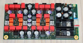
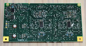
Done ... and it works
The board is finished now and works fine
 . So, the chips were real ones.
I attached a revised schematic with the resistor values i used. I also realised
that capacitors C13 and C58 should be connected to -VCC instead of GND,
allthough the board works fine with GND as well. I did not cjhange that on my
board but changed it in layout in the case i will build more boards.
As i can bypass the tone control via relays in my preamp i could make some
short hearing tests. I guess my ears are not golden enough. I could not hear
any difference between tone ON or bypassd.
Dirk
The board is finished now and works fine
I attached a revised schematic with the resistor values i used. I also realised
that capacitors C13 and C58 should be connected to -VCC instead of GND,
allthough the board works fine with GND as well. I did not cjhange that on my
board but changed it in layout in the case i will build more boards.
As i can bypass the tone control via relays in my preamp i could make some
short hearing tests. I guess my ears are not golden enough. I could not hear
any difference between tone ON or bypassd.
Dirk
Attachments
- Home
- Source & Line
- Analog Line Level
- 0.005% Distortion Tone Control Preamp, NJW1119A Chipset