Hello!
I'm new to this forum and looking for some help with my Sennheiser PC360 headset.
The potentiometer makes a crackling sound and I've read something about bypassing the volumeknob.
I know how to solder but I don't know which wires to solder. I've included a photo of the backside of the potentiometer. I really hope anyone can help me with this 🙂
Thanks in advance 🙂
I'm new to this forum and looking for some help with my Sennheiser PC360 headset.
The potentiometer makes a crackling sound and I've read something about bypassing the volumeknob.
I know how to solder but I don't know which wires to solder.
I've included a photo of the backside of the potentiometer. I really hope anyone can help me with this 🙂Thanks in advance 🙂
An externally hosted image should be here but it was not working when we last tested it.
If this was on the table in front of me it would be easy to figure out, identifying it from pictures much less so. It really is a case of just linking the control out, but its hard to make it out clearly.
What puzzles is that there are three wires entering. That could be stereo feed, L + R + common. I can only see two wires exiting (to other earpiece ?)
Could you do a clear picture looking straight at the circuit board perhaps ?
What puzzles is that there are three wires entering. That could be stereo feed, L + R + common. I can only see two wires exiting (to other earpiece ?)
Could you do a clear picture looking straight at the circuit board perhaps ?
Hi Mooly,
Thanks for your reply.
I think the sound enters at the two wires and exiting in 3 to the other earpiece.
I'm not at home so I can't make a picture at this time.
Thanks for your reply.
I think the sound enters at the two wires and exiting in 3 to the other earpiece.
I'm not at home so I can't make a picture at this time.
If I'm honest I can't just suss it out from your picture. The headset isn't mono surely ? just two wires as input ?
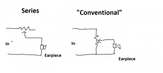
The control will either be in series with the earpiece or it would be wired as a true "volume control" with the earpiece feed taken from the wiper of the control. For stereo there would be two identical "gangs" on the control.
More pictures really, a close up of the PCB and an overview showing all the leads and earpieces and there leads.
This might help you figure it out. The control will be wired either in series or conventionally as shown here. For stereo you would double up on the circuit. So that three or four wires entering (there can be one common connection shared between the two channels)
For mono the two earpieces may just be series wired and connected to either arrangement of control.
For mono the two earpieces may just be series wired and connected to either arrangement of control.
Attachments
Well, to make it even wors, it's a surround set with bass. I will take a picture again as soon I'm at home 🙂
ps: could the mic have something to do with it?
ps: could the mic have something to do with it?
I wouldn't imagine the mic has any connection to this tbh. I think we'll have to wait and see what the pictures show and try and take it from there 🙂
Well, I hope this helps
Thanks in advance!
An externally hosted image should be here but it was not working when we last tested it.
Thanks in advance!
Last edited:
Thanks jerluwoo
Do those instructions make sense to you ? They don't to me... solder the two orange and the green together.
You can try it 🙂 It won't damage anything.
ncoma... those pictures seem to show its an inline series control. Only four of the 6 pins on the control seem to be used. Where is the wire to the left hand earpiece or is that soldered directly to the PCB.
Does each earpiece/speaker unit have just two wires going to it ? If so then what you need to do is take the - or negative terminal on each earpiece (as long as you use the same for both it doesn't really matter actually) and connect them together. That is then the "common" or ground.
There would be a corresponding contact patch on the earpiece for the left side earpiece, that mate with the open pads (I assume).
To bypass the volume use a short piece of wire on the pot pins. Counting down from the top of your picture, that would mean connect Pad 1 to 3 and 4 to 6.
To bypass the volume use a short piece of wire on the pot pins. Counting down from the top of your picture, that would mean connect Pad 1 to 3 and 4 to 6.
I connected the red in with the red out and the green/yellow with the yellow out and it all seems to work great! Sound is perfect!
Many thanks!
Many thanks!

Hi,
A small update.. the sound is working great! But when playing a game and there isn't any sound to play I hear a noise which I didn't have before.. It's a sound which build up like oise you can hear on your radio when you are between 2 frequenties. Did the pot-meter filter the noise before?
Sorry if you can't understand me. I'm from the Netherlands so english is not my native language. 🙂
I think I know what could be happening... maybe 🙂
Headphones can be very sensitive (you get a lot of sound for very little drive voltage) and so with the volume control bypassed you are hearing the inherent noise from your PC's audio stages. If so, then the fix is to make a small resistive attenuator. This can be either internal with the phones or external as an inline adapter 😱
You could just add a series resistor to each earpiece (trial and error on value, say start at 47 ohms and work upwards) or you could make a better "L Pad" attenuator.
L-pad Attenuator Tutorial for Passive Attenuators
For example (guessing values) make R1 a 33 ohm and R2 a 10 ohm. Still noise and to loud, reduce R2.
That is what I think is happening.
First of all, thanks so much for this thread. Solved my dirty potentiometer problem in a hurry! (Why these even have one to begin with is beyond me...)
The easy fix, is to solder bridge the four pins I have marked with the red line. I hope this helps the next person!
The easy fix, is to solder bridge the four pins I have marked with the red line. I hope this helps the next person!
An externally hosted image should be here but it was not working when we last tested it.
Last edited:
First of all, thanks so much for this thread. Solved my dirty potentiometer problem in a hurry! (Why these even have one to begin with is beyond me...)
The easy fix, is to solder bridge the four pins I have marked with the red line. I hope this helps the next person!

Hi there Chigger, i did what you suggested as it made sense this however broke the mic and now it isn't working. 😕
I'd like to know if this is exclusively an isolated issue or if you had this side-effect as well. Thanks a lot in advance.
JC
- Home
- Amplifiers
- Headphone Systems
- How to bypass volume potentiometer Sennheiser PC360