Dear members,
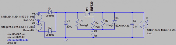
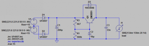
Please take a look at the attached very simple power supply ripple filter.
Key performance figures:
406 V offload voltage
134 mA quiescent current
14 mVpp ripple
These are comparable to a 15H choke (~100R Rdc), yet you can get all parts for the mosfet filter for less than 1€, compared to the price of a decent choke.
Am I missing something, or why are chokes still so popular in our tube amp power supplies?
Cheers
Attachments
I know, but chokes also have a Rdc, typically 100-200R. Voltage drop in this example would be about the Same...
Voltage drop is not the point choke store energy and reduce ripple by resisting change in current level . Chokes are big, heavy , expensive and inefficient. However they are very effective at the job . As well as increasing impedance vs freq. they are thus very different across the freq. range than the mosfet. 😎 Using mosfets for cap multipliers however does work well.I know, but chokes also have a Rdc, typically 100-200R. Voltage drop in this example would be about the Same...
The energy storage in a choke is incidental to its role as the series element in a low pass filter. Energy storage just happens to be the means by which a choke tries to maintain constant current.
Note that the follower shown in post 1 works in a different way from a choke; it is not a true series element as it has a ground connection via the 1uF capacitor. C2 and R1 are the low pass filter; the MOSFET just buffers the output from this. This circuit, unlike the choke, tries to maintain constant voltage, so it is not a choke replacement but an LC replacement.
Note that the follower shown in post 1 works in a different way from a choke; it is not a true series element as it has a ground connection via the 1uF capacitor. C2 and R1 are the low pass filter; the MOSFET just buffers the output from this. This circuit, unlike the choke, tries to maintain constant voltage, so it is not a choke replacement but an LC replacement.
Member
Joined 2009
Paid Member
Choke filters can also radiate noise into other areas of the amplifier through it's magnetic field.
I sometimes use MOSFET "choke filters", but often in my circuits the problem is voltage rating of the MOSFET.
For reliabilitys sake I like to have all the MOSFETs withstand the highest possible voltage that can happen at that position, and in the raw B+ filtering stages that can be 800 volts. It gets expensive.
Of course nowadays I mostly do fully balanced, where PSU filtering becomes an afterthought (there's still a regulator in there for 'final' B+).
Search for Mosfet Gyrator - the schematic posted above (as DF96 says) is NOT a simulated inductor supply, it is a simple capacitance multiplier.
The "real" gyrator supply emulates the chokes "resistance to current change" behaviour and is reputed to sound much better than a capacitance multiplier "ripple filter".
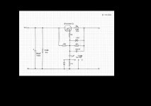
Here is one which can operate as a true simulated inductor (link out) or in a mode with reduced simulated inductor behaviour but capacitance multiplier function added (link in) - search "E-Choke" and you will find where you can buy this "off the shelf".
Cheers,
Ian
The "real" gyrator supply emulates the chokes "resistance to current change" behaviour and is reputed to sound much better than a capacitance multiplier "ripple filter".
Here is one which can operate as a true simulated inductor (link out) or in a mode with reduced simulated inductor behaviour but capacitance multiplier function added (link in) - search "E-Choke" and you will find where you can buy this "off the shelf".
Cheers,
Ian
Attachments

I would also echo Goldenbeer's question.
Whichever way the shown circuit works, he has posted the results, which as said would require a fairly large choke to equate. Heat loss vs. cost and inconvenience of a choke. It would be interesting to consider this alternative for a choke-input filter, where the "free-wheeling" spikes can be considerable as well as the induced interference (as mentioned) effect on nearby components. I had difficulty in getting the gap field far enough from circuitry to get rid of magnetic-induced effects.
Whichever way the shown circuit works, he has posted the results, which as said would require a fairly large choke to equate. Heat loss vs. cost and inconvenience of a choke. It would be interesting to consider this alternative for a choke-input filter, where the "free-wheeling" spikes can be considerable as well as the induced interference (as mentioned) effect on nearby components. I had difficulty in getting the gap field far enough from circuitry to get rid of magnetic-induced effects.
You can't use a FET to replace the choke in a choke input filter. A FET can't conduct current in the opposite direction to the applied voltage, as a choke can (for a while).
Thanks for your interesting contributions. First some remarks,
obviously, the mosfet filter is not equivalent to a choke. It's also not equivalent to a LC filter. It can be used instead of a choke or LC filter however.
It's also no gyrator for sure, and not meant to be one.
Thanks for pointing out the e-choke circuit, I will have a look into that one later.
Let's compare the mosfet filter performance to a classic CLC filter. I attached some pictures for this. I tried to make the circuits as similar as possible, but you will notice the CLC filter is not optimally configured. It shows quite some overshoot/ringing, but we will not pinpoint this as a disadvantage here, because a CLC filter can obviously configured to show no ringing.
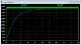
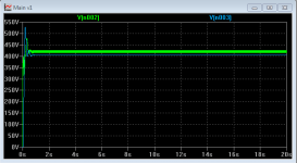
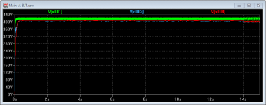
First is performance under constant load, in this case 134 mA. In all cases V002 is the voltage at the reservoir cap, and V003 at the output. There are two major findings.
The choke filter reaches steady state voltage quickly, and it's output closely resembles a sine wave.
The mosfet filter shows a slow start behaviour, and the output, though even less in ripple than the CLC filter, shows a more complex waveform with higher harmonics.
The biggest difference however is noticed under load, see next post.
obviously, the mosfet filter is not equivalent to a choke. It's also not equivalent to a LC filter. It can be used instead of a choke or LC filter however.
It's also no gyrator for sure, and not meant to be one.
Thanks for pointing out the e-choke circuit, I will have a look into that one later.
Let's compare the mosfet filter performance to a classic CLC filter. I attached some pictures for this. I tried to make the circuits as similar as possible, but you will notice the CLC filter is not optimally configured. It shows quite some overshoot/ringing, but we will not pinpoint this as a disadvantage here, because a CLC filter can obviously configured to show no ringing.
First is performance under constant load, in this case 134 mA. In all cases V002 is the voltage at the reservoir cap, and V003 at the output. There are two major findings.
The choke filter reaches steady state voltage quickly, and it's output closely resembles a sine wave.
The mosfet filter shows a slow start behaviour, and the output, though even less in ripple than the CLC filter, shows a more complex waveform with higher harmonics.
The biggest difference however is noticed under load, see next post.
Attachments

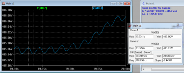

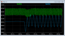
To check the behaviour under load, I simulated a current draw of +/-130 mA at 12 Hz. This represents kind of a worst case heavy load scenario for a class A amp.
The CLC filter responds with a heavy voltage swing, but the choke buffers the load from the reservoir cap and transformer effectively.
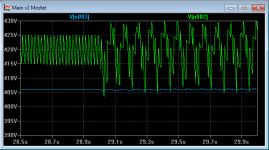
The mosfet filter shows very little reaction and no sag at all. However, heavy current is drawn from the reservoir cap, as shown by the V002 voltage swing. Essentially, the mosfet filter acts as a constant voltage source.
The CLC filter responds with a heavy voltage swing, but the choke buffers the load from the reservoir cap and transformer effectively.
The mosfet filter shows very little reaction and no sag at all. However, heavy current is drawn from the reservoir cap, as shown by the V002 voltage swing. Essentially, the mosfet filter acts as a constant voltage source.
Attachments
I am wondering if someone tried to upgrade their amplifier from CLC filter to MOSFET choke filtering. If so, I would appreciate they could share their experience if they like this modification.
Johnny
Johnny
Do you have some BJT part numbers Tor suggest? Also don't they need a heavy base drive, compared to a FET?
A 2N5551 feeds my 12ax7 pre amp stage via 560k and 10uF cap
A Tip112 will feed more current. A 55v zener prevents excessive VCE voltage on startup as the operating voltage across the transistor is a few volts
A Tip112 will feed more current. A 55v zener prevents excessive VCE voltage on startup as the operating voltage across the transistor is a few volts
that's close, the 560k (R3) goes from collector to the base
the zener goes from collector to base
a 150 ohm goes between C1 and the collector.
the 2N5551 works here with a 2.5 ma load from 12AX7
if you want to push 130ma use the TIP112 darlington and get rid of the 150 ohm current limiter
the zener goes from collector to base
a 150 ohm goes between C1 and the collector.
the 2N5551 works here with a 2.5 ma load from 12AX7
if you want to push 130ma use the TIP112 darlington and get rid of the 150 ohm current limiter
Thanks for your hints. However, I could not get it to perform to my satisfaction in ltspice. No matter what, the mosfet seems to perform way better. And, 2.5 mA isn't too hard to smooth even with CRC. But thanks anyway.
- Home
- Amplifiers
- Tubes / Valves
- Power supply mosfet vs choke filter