The subject of swapping op-amps is one of the more frequent topics to crop up on these forums... and regulars will know that I often add a proviso that you should ALWAYS check that the replacement is at the very least stable. Never assume it will be.
So here just to show what I mean is a simple op-amp swap of the sort that crops up on diyAudio all the time.
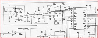
The circuit shown was designed for the NE5534 with no external compensation used on the op-amp. A typical scenario then, where everyone has their own ideas and favourites on what to fit. What could possibly go wrong... a double sided PCB with large ground planes with extensive decoupling and local regulators it is a model of impeccable layout.
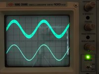
The opamp we are replacing is U30 that sums the output of the DAC. The two scope traces show the substituted op-amp as the top trace and the original as the lower trace. The scope was on the output of U30
The first picture is of the OPA604 FET opamp, one of my personal favourites. Straight away it is obvious that something is not right... the trace is "thicker", a classic effect of very high frequency instability. This was playing a 1khz track at around -40 db. The frequency of oscillation was around 1.8 Mhz and around 0.6 volts peak to peak.
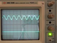
Second shot is the AD797 op-amp. Here the track played is 1 khz at 0db. As can be seen the op-amp is oscillating like crazy. To see just how crazy look at the next shot.
Third shot is the player in stop mode leaving just the oscillation. It's around 1.4Mhz but at a whopping 6 volts peak to peak.
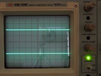
Fourth shot is the output of the op-amp with a 5pf cap across R33... clean with just a small amount of HF hash from the DAC itself that the following stage (the low pass filter) removes.
Would you know it was unstable by listening ? Well actually, you may not, and may put the change in sound down to the op-amp ! The AD797 certainly sounded over bright and thin but I can imagine some saying, "hey listen to that extra detail" it just shows how murky and dull the 5534 was. A bit extreme maybe, but you see my point.
The OPA604... far more subtle and many wouldn't notice the problem in a lot of systems.
So I hope that helps explain the "always check for stabilty etc" that I always trot out, and some of you reading this are probably doing so because I just linked your thread on "what should I replace xxxxxx with" to this one 😉
Happy swapping...
So here just to show what I mean is a simple op-amp swap of the sort that crops up on diyAudio all the time.
The circuit shown was designed for the NE5534 with no external compensation used on the op-amp. A typical scenario then, where everyone has their own ideas and favourites on what to fit. What could possibly go wrong... a double sided PCB with large ground planes with extensive decoupling and local regulators it is a model of impeccable layout.
The opamp we are replacing is U30 that sums the output of the DAC. The two scope traces show the substituted op-amp as the top trace and the original as the lower trace. The scope was on the output of U30
The first picture is of the OPA604 FET opamp, one of my personal favourites. Straight away it is obvious that something is not right... the trace is "thicker", a classic effect of very high frequency instability. This was playing a 1khz track at around -40 db. The frequency of oscillation was around 1.8 Mhz and around 0.6 volts peak to peak.
Second shot is the AD797 op-amp. Here the track played is 1 khz at 0db. As can be seen the op-amp is oscillating like crazy. To see just how crazy look at the next shot.
Third shot is the player in stop mode leaving just the oscillation. It's around 1.4Mhz but at a whopping 6 volts peak to peak.
Fourth shot is the output of the op-amp with a 5pf cap across R33... clean with just a small amount of HF hash from the DAC itself that the following stage (the low pass filter) removes.
Would you know it was unstable by listening ? Well actually, you may not, and may put the change in sound down to the op-amp ! The AD797 certainly sounded over bright and thin but I can imagine some saying, "hey listen to that extra detail" it just shows how murky and dull the 5534 was. A bit extreme maybe, but you see my point.
The OPA604... far more subtle and many wouldn't notice the problem in a lot of systems.
So I hope that helps explain the "always check for stabilty etc" that I always trot out, and some of you reading this are probably doing so because I just linked your thread on "what should I replace xxxxxx with" to this one 😉
Happy swapping...
Attachments


Very Good ,Mooly !
I had suspected such issues every time I had read a review of opamp swapping and the overly extreme critizism of some opamp types.
Good work! jer
I had suspected such issues every time I had read a review of opamp swapping and the overly extreme critizism of some opamp types.
Good work! jer
Good lesson, but what can do those who don't have a scope ?
(and how comes the NE5534 was used without compensation ?)
(and how comes the NE5534 was used without compensation ?)
Very good point - who wants to swap a 5532 with an LT1364 (yeah, i've just heard this a few days ago...) should keep it in mind.
L.
ps - Mooly, may I take your pictures to show them on another forum?
L.
ps - Mooly, may I take your pictures to show them on another forum?
Good lesson, but what can do those who don't have a scope ?
Get a scope. Seriously. Why in the world would someone try to do electronics without the basic tools? May as well try to get by without a soldering iron.
ps - Mooly, may I take your pictures to show them on another forum?
Well perhaps you could link another forum post to this... 🙂
(and how comes the NE5534 was used without compensation ?)
Because the circuit was designed to use the chosen device correctly.
Great post Mooly!
Swapping op amps ain't 'basic stuff' and I am sure this example along with a few others I can think of accounts for the 'gritty,nasty' sound some people claim.
This belongs in the Wiki.
Swapping op amps ain't 'basic stuff' and I am sure this example along with a few others I can think of accounts for the 'gritty,nasty' sound some people claim.
This belongs in the Wiki.
Well perhaps you could link another forum post to this... 🙂
Well, for sure, but you can't see the pictures unless you are registered to diyaudio
L.
A very well put together summary of what this Forum has been preaching almost since it started.
Thanks Mooly.
Thanks Mooly.
Well, for sure, but you can't see the pictures unless you are registered to diyaudio
L.
Thats a good reason to join diyAudio then 🙂
'cos between us all, I think we are the best 😉
OP amps should always be in band limited ciruits.
Best way is to have a capacitor in the feedback loop.
Best way is to have a capacitor in the feedback loop.
Only if its unity gain stable!OP amps should always be in band limited ciruits.
Best way is to have a capacitor in the feedback loop.
Don't forget the series output resistor if there is a capacitive load.
I also do not like the swappers habit of using IC sockets and stacked DIL-SMD converters. Video op-amps, which a lot of the > 10 MHz parts are, do not like the extra power supply inductance
[snip]Best way is to have a capacitor in the feedback loop.
Be careful! If you have an opamp or circuit that is not unity-gain stable, that cap will surely make it sing!
Such a feedback loop cap should only be used if you really know your circuit, like if you want to correct some phase shift elsewhere and not cause oscillations by decreasing the closed loop gain.
jan didden
Here are some guidelines from another post. Do just ONE of these things and you are likely to have problems. As noted above, the faster the op-amp, the more careful you need to be.
Happy 'op-amping'!
1. run a non-unity gain stable opamp at unity gain
2. run a decompensated opamp without a comp cap, or too small a comp cap for the gain setting
3. fail to fit an isolation resistor (usually about 50 Ohms) in series with the output when driving a real world load - like a cable for example, or a capacitive load.
4. fail to ensure that the junction of the feedback network is located physically very close to the op-amp feedback input pin (usually the inverting input)
5. fail to locate the input filter as physically close as possible to the op-amp input (usually the non-inverting input)
6. fail to decouple the supply rails adequately and close to the opamp supply pins
7. you use an opamp not characterized for wide band audio usage that has an inadequate slew rate
8. Fitting the comp cap across the wrong pins in an uncomensated op-amp (i.e 1-5 instead of 1-8 and vice-a-versa)
9. Failing to scope your physical design out . . . always follow Mooly's example
Thank you for pointing me this thread Mooly.
Suddenly I started to understand and correlate all the points I have read about (separatedly).
I also want to thank all involved for the clear and consise sharing 🙂
Suddenly I started to understand and correlate all the points I have read about (separatedly).
I also want to thank all involved for the clear and consise sharing 🙂
I don't like being brow-beaten (esp. by a moderator!) into spending $150-200 minimum on a tool that might get used once a year. Seriously. Is that unreasonable?Get a scope. Seriously. Why in the world would someone try to do electronics without the basic tools? May as well try to get by without a soldering iron.
(One of NP's early articles, A40, even has a suggestion on how to check DC at the outputs for the DIYer who HAS NO volt meter....!)
- Home
- Source & Line
- Analog Line Level
- Swapping Op-Amps... you have checked to see it's stable haven't you ?