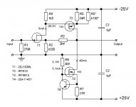
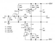
This schematics has no capacitors in the signal path, and demonstrates wide pass band even with standard easy obtainable parts.
Output voltage is rather stable, within 10mV. It is adjusted by the R5* resistor.
40mA idle current through T2 and T3 was choosen for using them without heatsinks. By adding heatsinks, the current can be encreased correspondingly by adjusting (decreasing) the R7.
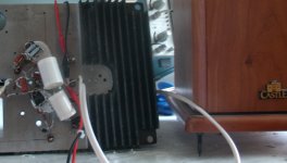
I put the schematics together on the breadboard, and made some measurements.
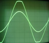
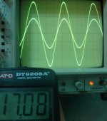
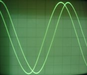
Maximum undistorted sine signal is 17V RMS, the clipping is nicely symmetric.
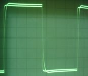
Also shown the 100kHz square wave (output amplitude is scaled to the input), and 1MHz input and output sine waves.
Output voltage is rather stable, within 10mV. It is adjusted by the R5* resistor.
40mA idle current through T2 and T3 was choosen for using them without heatsinks. By adding heatsinks, the current can be encreased correspondingly by adjusting (decreasing) the R7.
I put the schematics together on the breadboard, and made some measurements.
Maximum undistorted sine signal is 17V RMS, the clipping is nicely symmetric.
Also shown the 100kHz square wave (output amplitude is scaled to the input), and 1MHz input and output sine waves.
Attachments
Last edited:
It is not too often we see MOSFET in VAS.
But a pair of IRF610/9610 can deliver a good current with high speed.
Which shows in your images.
JFET at some mA will drive the GATES.
But a pair of IRF610/9610 can deliver a good current with high speed.
Which shows in your images.
JFET at some mA will drive the GATES.
It is not too often we see MOSFET in VAS.
But a pair of IRF610/9610 can deliver a good current with high speed.
Which shows in your images.
JFET at some mA will drive the GATES.
I also plan to transform this circuit into a real power amp - by using special high Idss, high transconductance, low-Ciss j-FETs, like CP650 (or russian KP903A), we can achieve 100-200mA in the first stage, and to use 3A idle current through T2,T3 (these could be K1530 and J201). The only doubt, the current from power rails under signal is not constant, hence some special care is needed to power supply design.
with a cascode and and lateral output sets it can scale to a beautiful Poweramp...
As for using laterals, I don't think it's a good idea, since with such a simle circuit we have to look for (transcondactance at idle current / Ciss) ratio, and hear Toshiba's MOSFETS seem to be more appropriate (or Fairchild's).
Ohh you misunderstand me
I would insert a cascode to shield the Jfet from higher voltage... and put the laterals after the mosfet stage...with a simple resistor as a bias spreader...
This is similar to my take on Lineups One J-fet amp which i Really like.... but i really like the use of mosfets for a single ended VAS...I think it would make a very good amplifier...
Attachments
Last edited:
I would insert a cascode to shield the Jfet from higher voltage... and put the laterals after the mosfet stage...with a simple resistor as a bias spreader...
This is similar to Lineups One J-fet amp which i Really like..and have made PCB's for.. but i really like the use of mosfets for the VAS...I think it would make a very good amplifier...
This is a good idea, but me personally I shall try to stay with two stages only (Nelson Pass's school ...).
Nelson Pass school, of one or two stages and HEXFET output.
But he is just about the only one that can get low dist that way.
And even he must make some clever patented tricks to get it there.
But he is just about the only one that can get low dist that way.
And even he must make some clever patented tricks to get it there.
As much as I like the simple Pass low wattage amplifiers, then he too uses extra stage(s) to get to higher power levels...
Member
Joined 2009
Paid Member
I say stick to your guns Vladimirk, build it simple and listen to it. I bet it'll sound great on a single large full range speaker - and will do so without being used above 1W.
Valdimir has an excellent idea perfect for pre-amps but we should not discount Miib's version which address a few problems in an innovative fashion.
Jam
Jam
Nelson Pass school, of one or two stages and HEXFET output.
But he is just about the only one that can get low dist that way.
And even he must make some clever patented tricks to get it there.
I would say, with his patents, Nelson possibly had in mind something other than distortions lowering. His tricky balanced schematics look for constant current consumption from PS rails under signal. This gives listenable sonic advantages, and THD and 2-d harmonic cancellation play very minor role in that. Schematics with much better THD figures frequently can sound much worse.
I have already convinced myself, after assembling and listening tenths of schematics, natural sound comes from, either due to using shunt PS, or due to specific measures, like balanced operation, or ciuffolli-like arrangement. Schematic itself, without PS added to the simulations, and without accounting for electromagnetic fields interaction - tiny effects influencing on the pulse responce, one can hardly estimate how the schematics will sound.
It could be useful to transform the schematics from post#1 into balanced one, with differential stage and balanced operation.
Last edited:
Member
Joined 2009
Paid Member
for me the interesting part here is the FET VAS, as I pointed out in another thread recently, it offers the potential of good linearity with a high input impedance and lower transconductance than a BJT which helps those not looking for 'too much' gnf - it would be interesting to learn of the results of an experiment that compared a FET with BJT in this position with all else being the same.
I have assembled for testing the power version of this schematics. J-FET current is 150mA, second stage idle current is 2A. Voltage amplification (near 7) is appropriate for direct connection to CD-player and loudspeaker.
Result is a bit dissappointing, I have got medium sound, like from hundreds of medium level hi-fi equipment. In similar listening conditions, the modified follower gave excellent sound from the very beginning. The issue of output cap is not decisive.
I have a guess how to improve the things, one needs shunt PS for the first stage and for the second stage. But, this will be more complicated and different story.
Error correction: T4 in this schematics must be shown by n-p-n transistor symbol.
Attachments
Last edited:
I have already convinced myself, after assembling and listening tenths of schematics, natural sound comes from, either due to using shunt PS, or due to specific measures, like balanced operation, or ciuffolli-like arrangement. Schematic itself, without PS added to the simulations, and without accounting for electromagnetic fields interaction - tiny effects influencing on the pulse responce, one can hardly estimate how the schematics will sound.
Imho (and I'm sure about it 😀) power supply is one key element for successful system. Simple circuit just need more in the power supply. The Aleph family with standard power supply will not make it. Upupa Epop will laugh at the distortion 😀 There is even something more important...
You have to see the system as one, not only the amp. No matter how good your amp, your speaker might anchor your system down. You think your amp is way better than the other amps simply because you cannot rely on your speaker. Once you have the "right" speaker, almost any good amp will do (even Gainclone), you just need to pay attention on power supply, distortion and the like. The vfet Ciss will most probably kill your whole system.
Big part of amps, that give no chance for laughing at the distortions, nevertheless can be deposited as trash. Thinking about hidden reasons, that could prevent one or another schematics from producing natural sound, seems most interesting for genuine DIYer. There are "superficial" features, like THD, IMD, output cap, pass band, and many of us tend to ascribe them an excessive importance.
I have PMC EB1i in the main system, that fit almost any high-end requirements, and in addition to SS amps, I also use SE 300B tube amp for estimating sound transparency. For on-the-bench tests, I use small Castle Acoustics Pembroke, that are very transparent nevetheless. And after assembling and testing of many schematics, I can state, the schematics that no shining at the first test, it could be improved at the final form (by using expensive PS arrangement etc.), but it will not become excellent. We need more real tests reports from DIY community. In this respect, my five cents, using of simple shunt PS, and providing constant current consumption from PS under signal, should be taken "to the surface" of DIYers attention. I heard from one professional designer, that these two points are also 100% confirmed in their practice.
In this respect, my five cents, using of simple shunt PS, and providing constant current consumption from PS under signal, should be taken "to the surface" of DIYers attention.
Yes. And buffers are good. They are simple, thus need a good supply. Shunt and/or choke is my favorite.
Have you heard people saying that bigger power amps tend to sound better? With high voltage power supply you are limited to using bad transistors, how can it be good??
Use BIG power supply, even if your amp is only rated at 30W, to avoid "current limited", "current blockade" or the like 😀 That's another five cents 🙂
Thank you, Jay, but it is a bit offensive to me, that people suppose that I could still learn such a things like you are saying.
I have got definite listening experience, of big amps, at various decent places, including "The Adelphi" in Singapore. Not many big amps sound good, compared to good tube ones. We understand, that good sound is not a loud or an agressive sound. Good sound = effect of presence at live event. Bad transistors - I tend to use good and very good transistors, including HF ones. They make sound very close to tube sound.
As for trafos, I use 1kVA per channel, for 30-50W class A amps.
Another cent on the PS effects: without choke and shunt PS, during the period when diodes are conducting, think where 10kHz alternating current peaks come from and why power cables are important, including rhodium plated connectors. Shunt PS allows to close this question.
Vladimir....Remember the Balanced version of your take on the 99 follower I posted....I'am becoming more and more sure that really would do the trick....Here in this version with the balanced PSU.. you get a set of Power supply caps directly in the current path for your speakers...On the follower you gave the DC blocking capacitor extreme attention...If you built the balanced follower with 30 V rail and 4 amps through each leg...You will have plenty of power and app burning the same energy like your current 50V version of the follower, but you will not have the need for the DC-blocking capacitor... A very pure approach..
- Home
- Amplifiers
- Solid State
- J-FET & MOSFET VAS with current NFB