Greetings.
I am shopping for replacement parts for this amplifier, I have Mr. Babin's repair tutorial, and am an experienced tech.
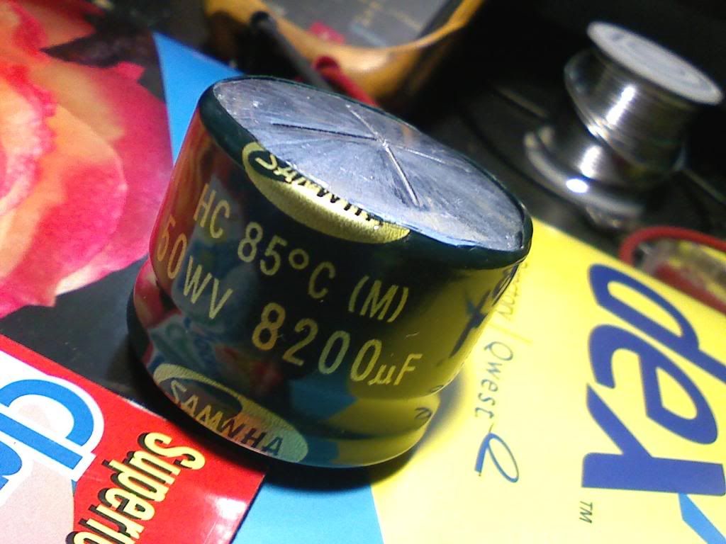
The first question I have is about the two large filter caps in said amp.
One is bulged and the other is not.
I intend to replace them both, along with a lot of other parts in here.
The max height with bottom cover installed is ~35mm.
Is this a suitable replacement?
Thanks for the help, and I will cover this repair completely in this thread for the next guy/gal to use...😀
paul
I am shopping for replacement parts for this amplifier, I have Mr. Babin's repair tutorial, and am an experienced tech.
The first question I have is about the two large filter caps in said amp.
One is bulged and the other is not.
I intend to replace them both, along with a lot of other parts in here.
The max height with bottom cover installed is ~35mm.
Is this a suitable replacement?
Thanks for the help, and I will cover this repair completely in this thread for the next guy/gal to use...😀
paul
Last edited:
I remember installing a few of those for my friends in high school (around '03). Great value for a used amp 🙂
I bought this one for $200 new in 2000 from an online discounter by the name of Yoshi.
It happily ran 2 alpine r's until 2005 when I quite accidentally turned it on with shorted speaker wire.
The smoke and fire was quite surprising, really.
I tried to fix it once replacing only the power supply fet's. I did not fully understand the cause and effect associated with these types of failures.
You can guess what happened when I powered it up.
So now I have all the info and am doing all the testing and we shall see what happens this time. 🙂
Ok.
I have the amp stripped of all fet's power and output.
Also have filter caps out and tl494 + 1266 drivers out.
Amp powers up fine.
Installed new filter caps, now it goes into protect.
Rectifiers are in, test good, and were never removed. All FET's/494/1266's are still out.
Normal?
paul
I have the amp stripped of all fet's power and output.
Also have filter caps out and tl494 + 1266 drivers out.
Amp powers up fine.
Installed new filter caps, now it goes into protect.
Rectifiers are in, test good, and were never removed. All FET's/494/1266's are still out.
Normal?
paul
Looking at the schematic diagram, it would appear that this is normal. Initially, the red LED is lit. It is driven off when the 494 begins to produce output.
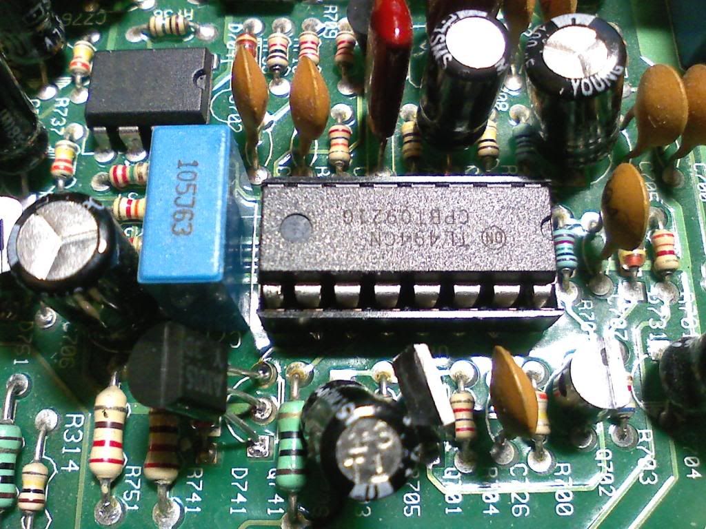
Ahh, 494 WAS in when I tested it last. It was overheating badly, so i decided to replace it.
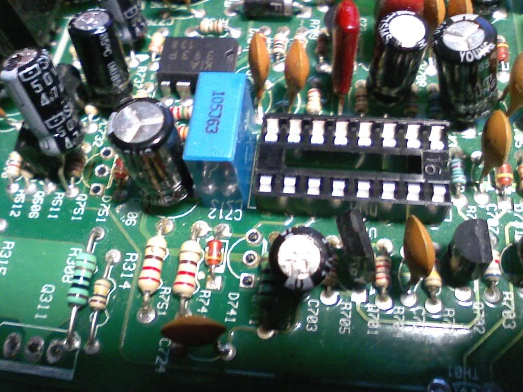
I used a socket..
I used a socket..
here are some pics to begin.
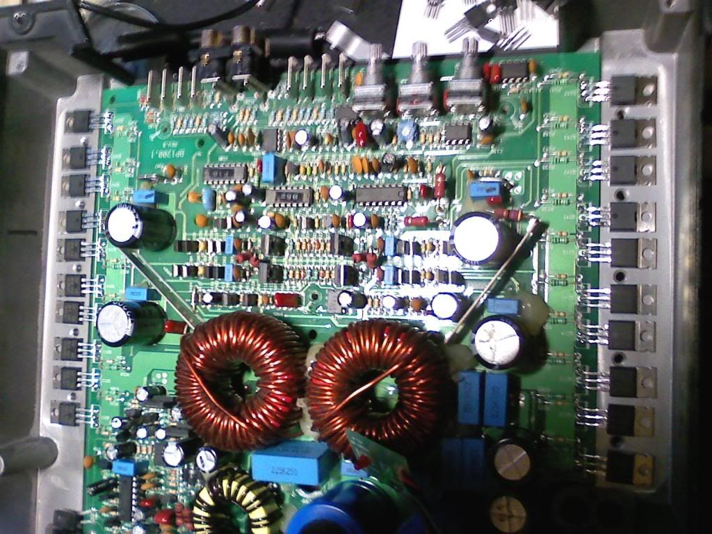
I replaced both filter caps:
with new, mouser sent wrong size but i used them anyway:
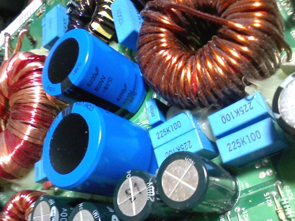
They are too tall for cover to fit properly, but not so tall that amp can't be mounted on flat surface.
I am going to have to modify the cover...
Here are some other bad parts:
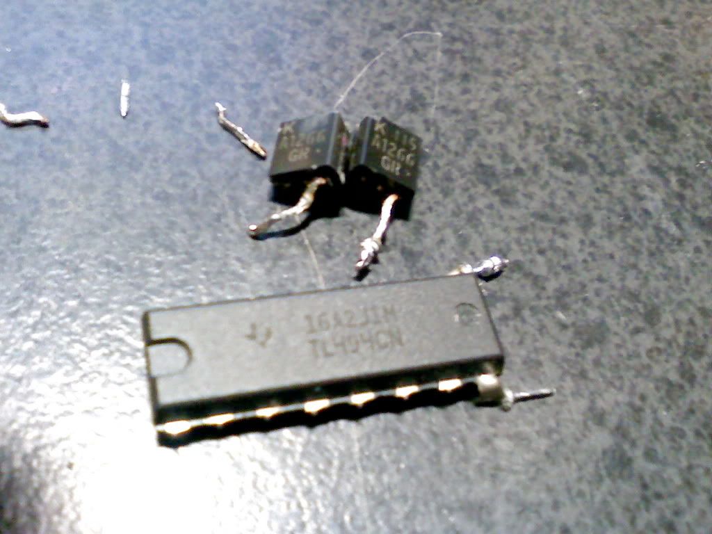
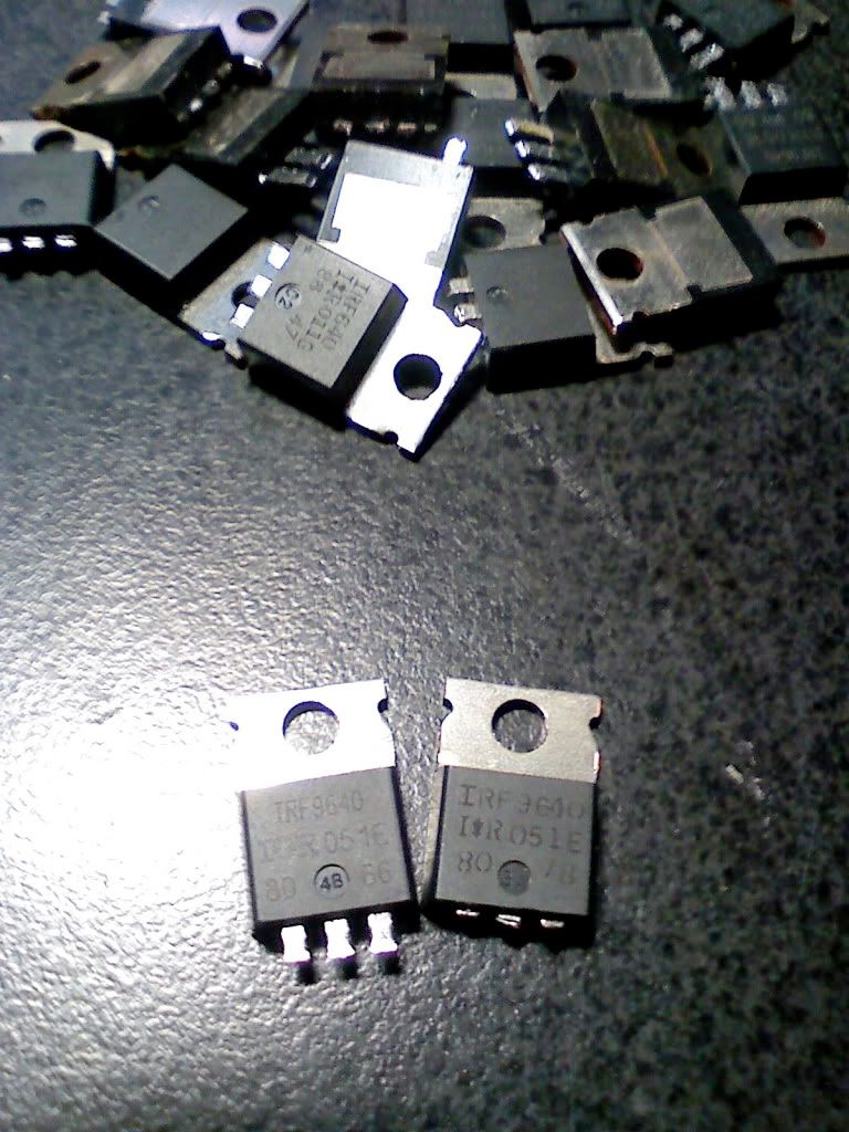
Q741 and q751 were shorted, and tl 494 got super hot as I was testing it. (Maybe I shorted pins🙄)
The 2 shorted irf9640's were the only outputs that were bad, but I decided to replace all fet's power and output BOTH sides. Irf3205's all exploded too, of course.
Socket installed:
Once I get the new tl494 in mail,
I am going to power it up and check for wave quality.
With no fet's installed, of course. I have a scope.
Any pin/procedural recommendations would be appreciated, and a good addition to this repair thread.
Thanks again all especially Perry for being here..
To be continued. . .
paul
I replaced both filter caps:
with new, mouser sent wrong size but i used them anyway:
They are too tall for cover to fit properly, but not so tall that amp can't be mounted on flat surface.
I am going to have to modify the cover...
Here are some other bad parts:
Q741 and q751 were shorted, and tl 494 got super hot as I was testing it. (Maybe I shorted pins🙄)
The 2 shorted irf9640's were the only outputs that were bad, but I decided to replace all fet's power and output BOTH sides. Irf3205's all exploded too, of course.
Socket installed:
Once I get the new tl494 in mail,
I am going to power it up and check for wave quality.
With no fet's installed, of course. I have a scope.
Any pin/procedural recommendations would be appreciated, and a good addition to this repair thread.
Thanks again all especially Perry for being here..
To be continued. . .
paul
It turns on normally, and I have a nice clean waveform at the place where the IRF 3205's gates get soldered!
Question,
Why would 4 640's, and 6 9640's be used per side of this amplifier instead of an even number of transistors N vs P ?
Maybe i missed it in the tutorial?
Question,
Why would 4 640's, and 6 9640's be used per side of this amplifier instead of an even number of transistors N vs P ?
Maybe i missed it in the tutorial?
Insulation time . . .
Hey,
I am about to clamp this and power it up, I was wondering about the polyamide/kapton tape.
This stuff is really thin and delicate, should I use more than one layer?
Do I have the wrong stuff?
OR
Should I just use sil pads again...?
Soldering is done..
paul
Hey,
I am about to clamp this and power it up, I was wondering about the polyamide/kapton tape.
This stuff is really thin and delicate, should I use more than one layer?
Do I have the wrong stuff?
OR
Should I just use sil pads again...?
Soldering is done..
paul
You definitely don't want to use more than one layer of tape. Unless you have a burr on the heatsink or on the back of a transistor (sometimes caused by people prying the transistors off of the sil pads), the kapton tape will be OK.
When you initially power it up, do so through nothing larger than a 15 amp fuse.
When you initially power it up, do so through nothing larger than a 15 amp fuse.
next step . . .?
Finally got the kapton tape I needed...
Power to 12+ and ground ok.
12.46 at b+
3.8~ at pin 1 of 494.
Put power to rem and it blows 10a fuse [3times].
I can't find a shorted transistor anywhere, and the power/output fet cases are not shorted to heatsink as far as meter suggests.
paul
Finally got the kapton tape I needed...
Power to 12+ and ground ok.
12.46 at b+
3.8~ at pin 1 of 494.
Put power to rem and it blows 10a fuse [3times].
I can't find a shorted transistor anywhere, and the power/output fet cases are not shorted to heatsink as far as meter suggests.
paul
** 1 of the filter caps is making noise and getting hot on 15A fuse.
had 1 in backwards...**🙄
Powers-up green light, now for the audio part😀
had 1 in backwards...**🙄
Powers-up green light, now for the audio part😀
Last edited:
"YOU WILL MAKE MISTAKES. You WILL short out components with your meter leads. You WILL install parts the wrong way (backwards). You WILL remove parts and forget where they go. All of these mistakes will lead to the destruction of parts and will be a gut-punch to your ego. It's not the end of the world when you make a mistake (but it will be annoying)."
I did. 🙂
Its going to cost me 10 FET's as far as I can tell...
It was working with small sub connected, had it running about half an hour.
Curiously, one side of outputs was getting hot while other was not. This was at ~20VAC/20HZ sinewave at speaker terminals and 15V at B+.
I did. 🙂
Its going to cost me 10 FET's as far as I can tell...
It was working with small sub connected, had it running about half an hour.
Curiously, one side of outputs was getting hot while other was not. This was at ~20VAC/20HZ sinewave at speaker terminals and 15V at B+.
- Home
- General Interest
- Car Audio
- JBL BP 1200.1 Project