Hello!
I hope someone of you can help me with the following problem:
Does anyone rember to the giant 1000 from elektor?
I have biult this amp but it makes some trouble.
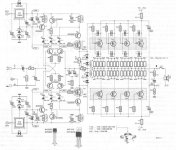
First of all i had to replace the original 2SK135/2SJ50 to the 2SK1058/2SJ162. Then i had to biult up a new PCB to fit the schematic on a 100x300mm card. The new layout is very similar to the original from elektor except that i mounted all MOSFETS and the voltage regulators on the same heatsink. Next i built the security schematic from the giant 2000 also from elektor, because its better then that one for the giant 1000. After that i tested the amp. Everthing works fine till the relay in the outputline conected the speaker to the amp. I hear a little hum and when i switch the amp off the relay falls after 5ms. In this time period, a very nasty and loud noise comes from the speaker.
Does anyoune built up this amp and made the same experience with it in the power-off sequence?
thx
PS: if you need more information, please ask.
I hope someone of you can help me with the following problem:
Does anyone rember to the giant 1000 from elektor?
I have biult this amp but it makes some trouble.
First of all i had to replace the original 2SK135/2SJ50 to the 2SK1058/2SJ162. Then i had to biult up a new PCB to fit the schematic on a 100x300mm card. The new layout is very similar to the original from elektor except that i mounted all MOSFETS and the voltage regulators on the same heatsink. Next i built the security schematic from the giant 2000 also from elektor, because its better then that one for the giant 1000. After that i tested the amp. Everthing works fine till the relay in the outputline conected the speaker to the amp. I hear a little hum and when i switch the amp off the relay falls after 5ms. In this time period, a very nasty and loud noise comes from the speaker.
Does anyoune built up this amp and made the same experience with it in the power-off sequence?
thx
PS: if you need more information, please ask.
togo said:Hello!
I hope someone of you can help me with the following problem:
Does anyone rember to the giant 1000 from elektor?
I have biult this amp but it makes some trouble.
First of all i had to replace the original 2SK135/2SJ50 to the 2SK1058/2SJ162. Then i had to biult up a new PCB to fit the schematic on a 100x300mm card. The new layout is very similar to the original from elektor except that i mounted all MOSFETS and the voltage regulators on the same heatsink. Next i built the security schematic from the giant 2000 also from elektor, because its better then that one for the giant 1000. After that i tested the amp. Everthing works fine till the relay in the outputline conected the speaker to the amp. I hear a little hum and when i switch the amp off the relay falls after 5ms. In this time period, a very nasty and loud noise comes from the speaker.
Does anyoune built up this amp and made the same experience with it in the power-off sequence?
thx
PS: if you need more information, please ask.
Schematics would be helpful.
Most amps give a thump through the speaker on turn off unless there is cctry to stop this.
togo said:except that i mounted all MOSFETS and the voltage regulators on the same heatsink.
Are the regulators and mosfets well isolated from the heatsink?
/Hugo
togo said:Hello!
I hope someone of you can help me with the following problem:
Does anyone rember to the giant 1000 from elektor?
I have biult this amp but it makes some trouble.
First of all i had to replace the original 2SK135/2SJ50 to the 2SK1058/2SJ162. Then i had to biult up a new PCB to fit the schematic on a 100x300mm card. The new layout is very similar to the original from elektor except that i mounted all MOSFETS and the voltage regulators on the same heatsink. Next i built the security schematic from the giant 2000 also from elektor, because its better then that one for the giant 1000. After that i tested the amp. Everthing works fine till the relay in the outputline conected the speaker to the amp. I hear a little hum and when i switch the amp off the relay falls after 5ms. In this time period, a very nasty and loud noise comes from the speaker.
Does anyoune built up this amp and made the same experience with it in the power-off sequence?
thx
PS: if you need more information, please ask.
I think the problem is just the capacitors in the PSU discharging and upsetting the amp cctry.
I have numerous amps both home built and bought in that give a thump on power up and power down.
My own designs use a microcontroller to hold the relay off for 3 seconds on power to get rid of the power up thump.
I suppose I should have added a mains detect cct that also detects when the mains goes away and then I can disconnect the speakers quickly.
What is the PSU and whats the meaning of cctry ?
I don't have a problem in the power up sequence.
The problem is the power down sequence.
I made some new meassurments on my amp:
When i switch off the amp, the +90V on the input of IC1 (7808) jumps from +90V down to +70V. The same happend on the output of IC1. Here the voltage jumps from +80V to +70V.
From +70V i meassure a slow unloading curve from the cap.
Why does it jump so steep from 90V to 70V ?
Is it in context with the diodes D17, D5 (D18, D6) ?
The schematic is over 25 years old so i ask myself: Are the diodes D17, D5 (D18, D6) on todays voltage regulators 7808 (7908) necessary?
togo said:What is the PSU and whats the meaning of cctry ?
I don't have a problem in the power up sequence.
The problem is the power down sequence.
I made some new meassurments on my amp:
When i switch off the amp, the +90V on the input of IC1 (7808) jumps from +90V down to +70V. The same happend on the output of IC1. Here the voltage jumps from +80V to +70V.
From +70V i meassure a slow unloading curve from the cap.
Why does it jump so steep from 90V to 70V ?
Is it in context with the diodes D17, D5 (D18, D6) ?
The schematic is over 25 years old so i ask myself: Are the diodes D17, D5 (D18, D6) on todays voltage regulators 7808 (7908) necessary?
PSU = power supply unit.
cctry = circuitry.
Hi Togo
One possibility would be that when you turn off your amp, a sparc builds up on your power switch which causes all sorts of ugly EMI interferences with your amp. I had exact this phenomenon on my DIY active speakers.
I got rid of this by installing a simple snubber (RC-Glied in German) in parallel to the power switch. Just make sure the snubber is at least rated for 250VAC. I would try a value like 22nF and 100ohm.
http://en.wikipedia.org/wiki/Snubber
Or you can use a so called "X2" capacitance instead of the snubber, again I would use a value like 10...47nF, maybe maximum 100nF:
http://www.wima.com/DE/mp3x2.htm
To test if it's really caused by the switch, you can switch off your amp by just unplug the wall plug. Then the nasty sound should be smaller.
Hope this helps
ntropy
P.S.: your relais falls of in 5ms, not 5s?
PSU = power supply and cctry is just short for "circuitry".
The diodes D17, D5 (D18, D6) are just standard protection diodes for the LM7808, you can find them under "typical applications" in all LM78xx datasheets.
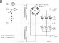
That you have a steep jump from 90V to 70V is a bit strange. How big are your capacitors in your power supply? (how many uF)
The diodes D17, D5 (D18, D6) are just standard protection diodes for the LM7808, you can find them under "typical applications" in all LM78xx datasheets.
That you have a steep jump from 90V to 70V is a bit strange. How big are your capacitors in your power supply? (how many uF)
Thx for your reply.
I have certainly testet this snubber a long time before, but it makes no different.
I have postet the schematic of the power supply.
The caps in there aren't very big.
So i have put in additional 100µ/100V on each side, and surprise it makes no different.
It is also very strange to me that i have this fall from 90 to 70.
I don't understand this amp 🙂
PS: the hole housing and hetsinks are conected with the ground from the psu 🙂
Attachments
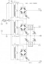
The +/- 90 are in series with the +/-12. What apparently happens is that the +/-12V discharge very quickly to zero, that automatically makes the +/-90 jump 12V downwards. If you increase the cap of the +/-90 that only makes it worse. You should increase the cap after the +/-12 bridge.
Jan Didden
Jan Didden
Post all schematics you have. I can't see for what the +/-12V is actually used. I would like to see as well how the 70...75V for the power stage is generated.
I would first measure if you can see this "jump" at the potentimeter P1 just to rule out that that it's not caused by the power amp stage.
I would first measure if you can see this "jump" at the potentimeter P1 just to rule out that that it's not caused by the power amp stage.
I have the complete set of articles on CD.
In the articles they warn about layout and in particular about how the drivers are heatsinked - I believe its something about capacitive coupling.
This is a CFA - so its very fast and without good layout you could have oscillation problems.
Read through the article carefully and take note of the construction guidelines
Bonsai said:I have the complete set of articles on CD.
In the articles they warn about layout and in particular about how the drivers are heatsinked - I believe its something about capacitive coupling.
This is a CFA - so its very fast and without good layout you could have oscillation problems.
Read through the article carefully and take note of the construction guidelines
I always ground my chassis and heatsinks.
The amps I have built have always been none critical about layout as they have been built on veroboard.
I am not surprised you do not have oscillation problems
1. Your designs are VFA
2. You have very high DC/LF gain (no degeneration resistors remember) and massive HF loop gain killing miller caps
Thse designs are a bit more amenable to veroboard construction. That said, you can still build good stuff on veroboard if care with grounding is taken.
CFA is an entirely different matter.
Please read the Elektor article - they are quite specific about not grounding the pre-driver and drive r heatsinks because of oscillation.
I jus t took a look at th e circuit above - it is not the Gigant I know.
I think Elektor published the 'Gigant' in Europe and one called the Titan in the UK. The Titan is CFA - the circuit above is VFA.
I think Elektor published the 'Gigant' in Europe and one called the Titan in the UK. The Titan is CFA - the circuit above is VFA.
Togo showed the plan of the GIGANT (500W at 4 Ohm).
It was published Mai 1986 in ELEKTOR (Germany).
I have the magazin here.
It was published Mai 1986 in ELEKTOR (Germany).
I have the magazin here.
I just checked - the one I have is Titan 2000 by T Geisberts. Also 500W into 4 Ohms but totally different circuit to the one above (many more components, CFA etc). Someone on the site about 2 or 3 years ago mentioned that this Titan 2000 was publisjed by Elektor in Germany and the Netherlands but under the name Gigant 2000 - I think thats why I got confused.
Here are the Specs of the Titan 2000
300W into 8 Ohms
500W into 4 Ohms
800W into 2 Ohms
Distortion .005% (no frequency or power level quoted)
SR 85V/uS
OL Bandwidth 55Khz
Power Bandwidth 1.5Hz to 220Khz (it uses a servo - hence the bottom end only going to 1.5 Hz)
Here are the Specs of the Titan 2000
300W into 8 Ohms
500W into 4 Ohms
800W into 2 Ohms
Distortion .005% (no frequency or power level quoted)
SR 85V/uS
OL Bandwidth 55Khz
Power Bandwidth 1.5Hz to 220Khz (it uses a servo - hence the bottom end only going to 1.5 Hz)
- Home
- More Vendors...
- Elektor
- Elektor-Giant 1000W