Hi folks,
I've owned this amp since '84 and recently decided to recap it with Panasonic audio grade electrolytics, on doing so i noticed a slightly cooked 1/2 watt resistor in the driver stage of one channel. The amp seems to sound fine, i can't detect any difference between channels, so for the meantime i upgraded the resistors to 1W metal films and the unit is in daily use. But the supply volts are down about 10 percent in 1 channel because of this so i think it needs to be sorted.The amp could have been this way for years, or even from new! I did lift the outputs off the heatsink and they do not overheat on idle so i think it is the driver stage. I fitted new darlington o/p's and the BC639 drivers but to no avail. I only have a slightly wrong cct kindly sent by Creek, but it is a poor scan and is blurred, hence i cannot give a cct ref for the 1K resistor. Mine is the 2nd version with the phono socket on the phono i/p and not the early one with 5 pin din. Has anyone got a better cct diagramme?
Also i would like to renew the speaker coupling capacitors, they are marked; Rubycon 3300uF, 35V, CEW, what is the best modern equivalents and where to obtain. I have access to CPC and RS components. If anyone has any ideas, they would be most appreciated.
Hi Bikelectro, greetings. I’m Al from near Coventry in the Midlands. Apart from an electrolytic breaking down, my series 1 cas4040 (bought 1984) has been a brilliant little amp. I play it now through B&W Signature 805s, as my better- healed pal says, the amp has no right to be this good. Your question is long solved or irrelevant by now, just wanted to give my regards. I started looking here as one channel has died tonight after me reconnecting a lose mains connector. All the semiconductors check out, speakers ok, but no startup thump on right channel. I shall be very sorry to lose this old friend if I can’t get to the bottom of the problem. All the best, Al
Alsslo with the power disconnected from the Amplifier and the top cover removed.
Check the speaker protection fuses located near to the speaker sockets.
The fuse may have failed or it could be loose in the fuse holder and not making a good contact.
Check the speaker protection fuses located near to the speaker sockets.
The fuse may have failed or it could be loose in the fuse holder and not making a good contact.
Thanks Audio Service! I had a look last night as I was hoping it might be the fuses. They conduct fine with a multimeter and the clips seem solid. I’ve also checked the diodes and semiconductors in circuit for diode behaviour. They all perform as expected. No components overheated and the electrolytics look in good shape - just as a first look. Speaker terminals don’t show open circuit on the meter either, although this could be the capacitor alone. Ah well, best put some days aside. Thanks for your help, any suggestions appreciated Audio Service
Alsslo can you check to see if you have the same issue with head phones, the head phones socket has switched contacts and is hard wired to the speaker output sockets.
Creek Cas4040 diagnostics
Hi Audio Service, sorry for the delay, I had the amp in bits and had to find working headphones and adaptor. Right channel is also out on headphones, I've tried with diverse inputs. Distinct mains hum is heard on the right channel, left is fine. Speakers thump both sides on startup, right channel somewhat stronger. Ill load a pic of the capacitor and semiconductor measurements when I've tidied up the pic. Thanks!
Hi Audio Service, sorry for the delay, I had the amp in bits and had to find working headphones and adaptor. Right channel is also out on headphones, I've tried with diverse inputs. Distinct mains hum is heard on the right channel, left is fine. Speakers thump both sides on startup, right channel somewhat stronger. Ill load a pic of the capacitor and semiconductor measurements when I've tidied up the pic. Thanks!
Creek 4040 channel down, low mains buzz
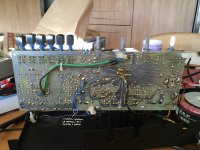
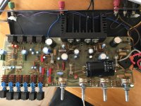
Hi, Audio Service, here are the pictures of the Creek 4040 board, and the equivalent series resistance measurements. There are a few electrolytic caps out of spec, and I'll change those. The semiconductors all seem to be performing fine on the diode test. There is some evidence of heat damage to the underside of the board near the OP darlington pairs (left channel). I'll change these, off spec electrolytics and see where to go from there . The RH channel (RHS on the board pictures) has a background hum and noise, not load. Anybody, any other ideas on where to go from here?
Thanks!
Al
Attachments
Thank you for the additional information, do you have a scope of audio signal tracer?
We need to check the Audio signal(s) entering and existing the volume control.
We need to check the Audio signal(s) entering and existing the volume control.
Will do, I'll set up and get back to you in a few days. No signal comes out of rh channel, just low mains hum and some noise.
Oscilloscope traces for Creek 4040
Hi Audio Service, thanks for your support. I've input a 1kHz signal to the aux input (other inputs give a similar result) and used an oscilloscope to trace the signal before and after the volume control. Here are the images, together with some others to make sense of the results:
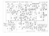
1. Circuit diagram kindly sent by Mike Creek a few days ago. It should cover my serial number (CAS:6366, board number 1027), but my power transistors are BDT65B and BDT63A, not BDT62C and BDT63C as shown.
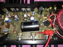
2. Photo of the volume control section with C14 and C104 shown. The input signal was taken from the negative end of each.
3. Trace showing LH channel input to the volume control. The pot centre contact also showed the signal
4. Trace showing RH channel input to the volume control. The pot centre contact also showed the signal.
5. LH channel speaker output shows 1kHz output. Headphones were connected in at the time.
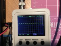
6. RH channel speaker output shows a low deformed output on the same timebase settings as picture 5 with trigger adjusted to show a trace. No trace of 1kHz heard on headphones.
I'll trace further through from the volume control, but really appreciate your support. What do you suggest next? Cheers! Al
Hi Audio Service, thanks for your support. I've input a 1kHz signal to the aux input (other inputs give a similar result) and used an oscilloscope to trace the signal before and after the volume control. Here are the images, together with some others to make sense of the results:
1. Circuit diagram kindly sent by Mike Creek a few days ago. It should cover my serial number (CAS:6366, board number 1027), but my power transistors are BDT65B and BDT63A, not BDT62C and BDT63C as shown.
2. Photo of the volume control section with C14 and C104 shown. The input signal was taken from the negative end of each.
3. Trace showing LH channel input to the volume control. The pot centre contact also showed the signal
4. Trace showing RH channel input to the volume control. The pot centre contact also showed the signal.
5. LH channel speaker output shows 1kHz output. Headphones were connected in at the time.
6. RH channel speaker output shows a low deformed output on the same timebase settings as picture 5 with trigger adjusted to show a trace. No trace of 1kHz heard on headphones.
I'll trace further through from the volume control, but really appreciate your support. What do you suggest next? Cheers! Al
Images 2, 3,4,6 Creek 4040 s1


Order:
Volume control area with caps
Signal at LH channel input to volume control
Signal at RH channel input to volume control
Loudspeaker output for RH channel (headphones connected)
Order:
Volume control area with caps
Signal at LH channel input to volume control
Signal at RH channel input to volume control
Loudspeaker output for RH channel (headphones connected)

Q3 and Q103 not so easy... I must be introducing some load dropping the signal (but didn't affect the headphone sound, LH still with 1kHz tone), but Q3 initially did give a low mv sine wave, and Q103 not on my old scope. Tested at -ve end of C32/C132 before C18/C118, which confirms sine on LH and noise/no sine wave on RH channel.
To check further down the line, collector of Q4 (BFR39 on my amplifier) shows sine wave, Q104 only noise.
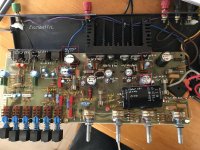
1. Markups around (L to R) balance, treble and bass pots
2. Top of C32 (-ve end) leading to -ve end of C18 (sine wave)
3. Top of C132 (-ve end) leading to -ve end of C118 (no sine wave)
Markups of resistors and signal around balance/treble/bass pots attached.
Thanks Audio Service, learning a lot!
Regards, Al
To check further down the line, collector of Q4 (BFR39 on my amplifier) shows sine wave, Q104 only noise.
1. Markups around (L to R) balance, treble and bass pots
2. Top of C32 (-ve end) leading to -ve end of C18 (sine wave)
3. Top of C132 (-ve end) leading to -ve end of C118 (no sine wave)
Markups of resistors and signal around balance/treble/bass pots attached.
Thanks Audio Service, learning a lot!
Regards, Al
Attachments

- Home
- Amplifiers
- Solid State
- Creek CAS 4040 problems and speaker coupling electrolytic query