Dear All,
Anyone used Vacuum State dpa300B power amp before?
Any comment on it?
I'm now consider to buy this power amp.
Thanks a lot!
Best Regards
Anyone used Vacuum State dpa300B power amp before?
Any comment on it?
I'm now consider to buy this power amp.
Thanks a lot!
Best Regards
Re: Any comment on Vacuum State dpa300b??
I am about to start building a pair of these amps. At the moment I am busy building Allen Wright's RTP3D preamps.
Are you considering building a kit, or are you going to be buying the DPA-300B amps ready built?
I am about to start building a pair of these amps. At the moment I am busy building Allen Wright's RTP3D preamps.
Are you considering building a kit, or are you going to be buying the DPA-300B amps ready built?
In theory the DPA300B should be one of the finest amps availble. I based my current amp design on the differential aspects of this amp. I also built a version of the FTP5 preamp and the sonic characture of this preamp is very pure. I would guess that the DPA300B is probably the nearest to wire with gain that its possible to get in the field of Valves.
Shoog
Shoog
Shoog said:I would guess that the DPA300B is probably the nearest to wire with gain that its possible to get in the field of Valves.
It may be. One of the misgivings I have about the design is that it is actually too good. It promises to be an amp that can really deliver what has been very difficult in practice: an amp that can preserve all that important delicate detail, isn't fatiguing to listen to, but isn't thin in the bass like many SE amps are.
But what about all those juicy harmonics? To borrow Allen Wright's metaphor, maybe I do want chocolate sauce on everything. I mean, what is the point of building a valve amp where the valves are so tightly bootstrapped? It's sort of like not letting valves be themselves, in a manner of speaking.
But it's worth doing, because for me the alternative is trying to build Lynn Olson's Karna amp, which would mean sourcing every component myself, and having to set up a small workshop to make a chassis, and I really don't want to do that.
Funny you should mention the Karna amp. My current amp uses the differential aspects of the dpa300B, and the interstage phase splitting of the Karna.
I know what you mean about wanting a bit of distortion - but to be honest my experience is that valves are intrinsically the least distorted amplifiers of the lot and its only poor design that allows distortion in.
PP is definately the way to go. Its not so much that the bass is thin in SE designs, more that its woolley and indestinct. I think that a design like the Karna or dpa300B will produce the type of midrange detail of a SE, but without the high frequency roll off which makes it sound to smooth for my taste.
The woolley bass of SE can also be attributed to a lack of ultrasonic detail which has the effect of adding the snap into bass passages.
Shoog
Snap. That's the word I was looking for. It's reassuring to hear that the DPA-300B could deliver the midrange I'm after. I sure hope so, because kit or no kit, these things are by no means that easy to put together. Well, not the RTP3D preamp, anyway. Because of the latest design change, the component count has crept up, and things are getting rather crowded.
I've seen a discussion on a forum somewhere contrasting Allen's and Lynn's design philosophy; interstage transformer coupling contrasted with RC. In some ways I like Lynn's design more. There's an irony in taking a 1930s Western Electric design and combining it with technology unavailable at the time -- SS-based constant current sources. It's making some kind of statement about being true to proven designs but across a long timespan.
I've seen a discussion on a forum somewhere contrasting Allen's and Lynn's design philosophy; interstage transformer coupling contrasted with RC. In some ways I like Lynn's design more. There's an irony in taking a 1930s Western Electric design and combining it with technology unavailable at the time -- SS-based constant current sources. It's making some kind of statement about being true to proven designs but across a long timespan.
From my reading - anyone who has heard interstage transformer phase splitting would never ever go back to RC coupling. Unfortunately these transformers as very expensive and need serious drivers to get them to give of their true potential. Beyond the the scope of most single build DIYers.
Most bottleheads seem to avoid CCS because they think they want that distorted sound. I use CCS where ever I can put them. Even a triode based CCS brings benefits, and its the lowest performing one of the lot (you would already know that from your preamp build).
Shoog
Most bottleheads seem to avoid CCS because they think they want that distorted sound. I use CCS where ever I can put them. Even a triode based CCS brings benefits, and its the lowest performing one of the lot (you would already know that from your preamp build).
Shoog
Hi Shoog
I think you are referring to the amplifier with the ECL82 and 6AS7, that, if I remember well, was trafo coupled between ECL's pentode and 6AS7? Other thing I remember is that you were using individual LM317's per triode of the 6AS7. Do you still use individual, or are you using one single LM317 configured for 200mA CCS? (I imagine that one single LM317 would be more like the DPA300B.)
Erik
My current amp uses the differential aspects of the dpa300B, and the interstage phase splitting of the Karna.
I think you are referring to the amplifier with the ECL82 and 6AS7, that, if I remember well, was trafo coupled between ECL's pentode and 6AS7? Other thing I remember is that you were using individual LM317's per triode of the 6AS7. Do you still use individual, or are you using one single LM317 configured for 200mA CCS? (I imagine that one single LM317 would be more like the DPA300B.)
Erik
Shoog said:My current amp uses the differential aspects of the dpa300B, and the interstage phase splitting of the Karna.
Is it the final stage of your amp that resembles that of the DPA-300B? If so, why?
Martin Hayes said:contrasting Allen's and Lynn's design philosophy
I know Allen has great respect for Lynn... him and Lynn were sharing hotel space at the last VSAC, Allen was traveling on foot and wasn't able to bring his amp when he came to visit. My buddy Chris did hear it, it caused a lot of ripples for those that heard it.
When we are considering building PP amps this design always serves as one of our reference designs ... one of these days i hope to build one.
dave
I think you are referring to the amplifier with the ECL82 and 6AS7, that, if I remember well, was trafo coupled between ECL's pentode and 6AS7? Other thing I remember is that you were using individual LM317's per triode of the 6AS7. Do you still use individual, or are you using one single LM317 configured for 200mA CCS? (I imagine that one single LM317 would be more like the DPA300B.)
I'am still using the two LM317's per side. This is absolutely essential with the 6AS7 because of poor side matching and so the need to keep perfect balance.
I have recently increased the current through the pentode section of the ECL82 from 25mA to 40mA, this has allowed me to eliminate one loop of feedback, and has filled out the sound considerably. As a result the ECL82 has gone up in my estimation somewhat.
Things have been going well with this amp for the last 8months or so. Infact i'am so happy I can't motivate myself to build anything else. I have the idea to build a different version using PL84's(EL86'), which would allow me to eliminate all feedback and use more linear tubes - but really I can't be bothered to drag everything together just yet. The 6AS7 has its issues with linearity but its got such a low output impedance that it gives good damping without gNFB. The same cannot be said for many other valves and certainly wont be as good with the PL84's.
Is it the final stage of your amp that resembles that of the DPA-300B? If so, why?
As pointed out a single LM317 per channel would be more like the dpa300B, but the design principle is similar. I think Allen will be using a different circuit to achieve the differential aspect of the output stage. I simply borrowed from his approach.
Shoog
Shoog
Many thanks for the reply. Your approach with the LM317's is still something I want to try, but little time due to study, work and so on.
Erik
Many thanks for the reply. Your approach with the LM317's is still something I want to try, but little time due to study, work and so on.
Erik
I was thinking somewhat further on the use of a single CCS in the tail of the two output tubes in a PP design, and the question arose on how one can achieve a perfect DC balance, that is, that the current drawn through each tube (and corresponding trafo winding) is the same?
Erik
Erik
This is why I don't do it !!
I like the fact that two CCS means you never have to worry about matched pairs, or twiddling with balance pots.
However it is possible and simply requires the addition of a balancing pot
Heres an example;
http://www.diyparadise.com/buildel84c.html
Hope that helps.
Shoog
I like the fact that two CCS means you never have to worry about matched pairs, or twiddling with balance pots.
However it is possible and simply requires the addition of a balancing pot
Heres an example;
http://www.diyparadise.com/buildel84c.html
Hope that helps.
Shoog
Thanks Shoog
Someday I will just build both ways, and compare, sonicwise. I know there must be a difference between both as the 'one CCS' option (as the one from the link you posted) does not need decoupling caps... Until then I will just keep my mouth shut and stop threadjacking.
Erik
Someday I will just build both ways, and compare, sonicwise. I know there must be a difference between both as the 'one CCS' option (as the one from the link you posted) does not need decoupling caps... Until then I will just keep my mouth shut and stop threadjacking.
Erik
Here are some variations-on-a-theme that I’ve toyed with in years past for using a CCS in the tail of an output PP pair. I’m not quite sure which of these Shoog is talking about.
A.) The simple single CCS. Possible imbalance between sides. Good common-mode and power-supply rejection. No caps. Works to “DC”. Class A only.
B.) Adds the adjustment that you were talking about to equalize the tubes, but drift will still occur over time. Class A only.
C.) Small current sampling resistors will develop a differential voltage if there is a current imbalance, and a servo chain provides a correction through a large grid resistor to one side only. Adds a low-frequency pole. Class A only. Rejection is still good.
D.) Two CCSs keep each tube’s DC current locked in to a set current with no drift, but a cap between cathodes is needed to make the pair work as a differential pair. Common-mode and power-supply rejection is still good, but there is a low-frequency pole and the sound of a cap.
E.) Same as “D” but shows how to connect a pair of large electrolytics and one small film cap to get the capacitance needed to couple the cathodes to very low frequencies. Note that the electrolytics need not be grounded - a 1Meg resistor (or so) keeps a DC bias on them, but it is so large that common-mode and differential mode rejection is still excellent. I haven’t seen this technique used before, but it probably has been.
F.) A version of “A” which will allow Class AB operation, but keeps the DC sum of currents constant. Rejection is now poor.
All versions with caps enable operation beyond Class A into Class AB, but also risk capacitor charge shift from overloads (blocking or bias shift). They also add low-frequency poles. There is no free lunch.
Attachments
Thanks Brian,
My setup is like "E", but with film bypassed electros seperately from each cathode to ground. I might try changing it to your configuration to see if there is any sonic benefit. I appreciate that my current configuration isn't really differential at all, but it is much better than just bypassed resistors.
Did you ever try it with just big caps to ground - if so how did it compare? What was the best sonic result overall?
Very useful information.
Thanks
Shoog
Hi again,
I just tried plan "E" (a matter of five mins to lash up). Unfortunately it seemed to shift the balance of amp into been to bright.
I can only guess that this has something to do with the quality of the LM317 CCS which is not very good. When using a cap to bypass it completely this is of little importance as it is largely out of the picture. However in Plan "E" I would guess that the quality of the CCS is far more important as it isn't bypassed as completely. Of course it could be some other circuit related factor. I am using 1000uf caps on each cathode - are they big enough ??
I would also hazard a guess that it increases the output impedance over a straight bypass, and so reduces the damping of the output stage.
Shoog
Shoog,
I neglected to show the option that I think you’re using. I’ve attached it as option “G”, as well as a variant I labeled option “H”. And I’m sure that there are even more.
There are so many factors that can influence sound, not the least of which is the type of basic circuit into which you’re introducing these CCS options. I would not want to say that option “E” intrinsically sounds bright or whatever else as a generalization. These are simple tools with no particular sound, or rightness or wrongness by themselves. As always, it depends.
Can you post your schematic? I have no idea what your circuit looks like. Class A or Class AB?
I will say that “E” has some POTENTIAL advantages over “G”, but these may or may NOT be helpful in your particular circuit, and it has one big disadvantage (see below).
Let’s consider Class A first (or the first few watts in a Class AB amp): Ignoring the CCSs for a minute, the two cathodes must see the same AC signal, for true differential or push-pull behavior. In “G”, the AC signal on one cathode is connected to the other cathode through its bypass cap(s), through ground, to the other bypass cap(s) to the other cathode. Cap imperfections such as ESR and ESL are doubled in this series connection, as far as the differential signal is concerned. There is also now a cathode reference to ground making it sensitive to common-mode signals (and reducing power supply rejection), for better or for worse. In “E” the caps are free of ground (or nearly so by virtue of the large resistor) and can float in a common-mode sense. The PP stage is now nearly immune to common-mode input signals, and power supply rejection is much greater. The cathodes are tied to each other at low and middle frequencies by the two large series electrolytics (the same as in “G”), but at high frequencies the single film cap ties the cathode more tightly together, with half the ESR and ESL of two separate caps. Note also that a single 0.5uF film cap tied directly between cathodes is like having two separate 1uF caps across each cathode due to the series effect.
A big difference lies in Class-A versus Class-AB behavior. For Class AB, you’d want the bypass caps to be connected to ground to give the hard-driven tube a cathode reference when its grid is driven high. With floating caps (“as in “E”) the hard-driven tube loses its cathode “anchor” when the other tube stops conducting. For Class A operation, “E” should win out. But for Class AB, perhaps option “H” is the most promising. Option “H” is a simple variant of “G” having the benefit of a single small high-quality cap connecting the two cathodes at high frequencies. You can augment “H” with two additional film caps across the electrolytics, giving film bypasses for differential mode and also to ground for when one tube stops conducting in Class AB.
Attachments

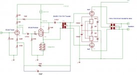
It is indeed option "G".
I have attached the last circuit I had drawn up. The output stage is running in pure class A. I am now pushing 40mA through the pentode and have substituted a simple resistor for pentode bias. I have removed the cathode feedback loop and added 100K resistors on the secondaries of the interstage transformer to calm some ringing.
There was a shift in tone with plan "E" (reminds me of Plan 9 from outer space). Of course it could be revealing a problem with the circuit that was hitherto hidden. Do you think it could be the LM317's.
Unfortunately my scope has just went dead and so I cannot test anything empirically.
Shoog
Attachments
- Home
- Amplifiers
- Tubes / Valves
- Any comment on Vacuum State DPA300B?