My version of the RIAA circuit is 1/10th the impedance, using 88.8k || 36nF, 7.5k || 10nF, and a 91R : 10R output attenuator for MC. This gives a more representative source impedance for MC (and lower noise floor of 0.4nV/√Hz).
I added 1k + 0.45H impedance in series with the MM output to mimic typical cartridge impedance for more representative noise measurements too.
I further refinement was being able to switch in 10k instead of the RIAA section to give just a flat response attenuator too.
I added 1k + 0.45H impedance in series with the MM output to mimic typical cartridge impedance for more representative noise measurements too.
I further refinement was being able to switch in 10k instead of the RIAA section to give just a flat response attenuator too.

I added 1k + 0.45H impedance in series with the MM output to mimic typical cartridge impedance for more representative noise measurements too.
Really clever move with the 1k + 0.45H. It mimics the complex impedance of an MM cartridge much more realistically than just resistive loading. That should give a more accurate look at input-stage noise performance in phono preamps. I kept the network at standard RIAA impedance levels mainly to match typical phono input loads and to preserve compatibility with basic bench gear, but I like the idea of building a low-Z version specifically for noise floor testing.
Out of curiosity, did you find any noticeable shift in frequency response compared to a flat resistive source? Or did the loading just mainly impact noise floor?
Inspiring approach overall 👍
The 910 ohms of the divider for MC output swamps any MM output impedance which is at least 47k typically.
Do multiple samples in series/parallel taken from the (presumed) same production run actually average towards the bogie value, or do we still need "known" values and a way to measure them? Asking for a friend.
Lost in toleranceville,
Chris
ps: I'm sorry if the references are too obscure. You probably need to be old enough to be a John Prine fan and know his song Dear Abby, best on his 1988 live album.
Signed, Dear Abby
Lost in toleranceville,
Chris
ps: I'm sorry if the references are too obscure. You probably need to be old enough to be a John Prine fan and know his song Dear Abby, best on his 1988 live album.
Signed, Dear Abby
Last edited:
Mark, I hope you can short your 1 kohm and 450 mH for frequency response measurements, otherwise the effect of the LRC network will be counted twice, once by you and once by the cartridge manufacturer.
In principle, it's the cartridge manufacturer's responsibility to ensure a flattish response from the record to the cartridge output when the cartridge is loaded with the recommended load. That is, the combination of the mechanical and the electric (LRC) transfer has to be sort of flat. The phono preamplifier just has to have the right input impedance and the right (RIAA) response from the voltage across its input terminals to its output.
In principle, it's the cartridge manufacturer's responsibility to ensure a flattish response from the record to the cartridge output when the cartridge is loaded with the recommended load. That is, the combination of the mechanical and the electric (LRC) transfer has to be sort of flat. The phono preamplifier just has to have the right input impedance and the right (RIAA) response from the voltage across its input terminals to its output.
Do multiple samples in series/parallel taken from the (presumed) same production run actually average towards the bogie value, or do we still need "known" values and a way to measure them? Asking for a friend.
Dear Chris (Abby), statistically speaking, averaging samples from a consistent production run can help reduce random variation, assuming Gaussian distribution and no systemic drift. But in the real Toleranceville world, unless the bogie is tightly defined and verified, you're still flying blind without a known-good reference or calibration method.
Parallel hope, serial doubt.
Still measuring, not guessing. 🍻
I'm currently (and verrrrry lowly) in the process of building a ragtag prototype of the MvdG phono stage and a (better-than-my-1976-possibly-still 1dB ?) reverse RIAA lossy network, or better than is built into a Sound Technology 1200. Intent is to make a Lipshitz/Jung (883K) with 600 Ohm-ish R3. Can I assume (yes, I know) that I could reduce R3 arbitrarily without significant change to the important mid-band inflections?
All good fortune,
Chris
All good fortune,
Chris
Hi Alan,
Very nice and neatly executed project, congrats!
Since your are in precision, I can only drop a hint about components choice. For capacitors there are 1% polystyrene extended foil (extended foil means minimal inductance) caps, they are not in production for long time, but can be found, made by RIFA (PFE series) in 80's. Except they need to be found , they are also large, complicated all together but as far as I know the best filter cap ever.
Recently I finished preamp with passive RIAA and achieved max 0.04db mismatch between channels by using those, 0.05% resistors, and where I could not get exact value: hand picked from 2% resistors to reduce number in network.
Here is link showing deviation from left and right channel. I did not measure absolute riaa accuracy, but since components and math are right, there is no need to doubt. PS, in that post I mentioned 0.3db mismatch, think I was tired then, it is one zero more.
https://www.diyaudio.com/community/...ono-preamplifier-thoughts.414816/post-8035424
PS, Few good people here mentioned need of matching input and output impedance's here , IMHO excellent advice to make your tool even more usefull
Best,
Drazen
Alan,
I simulated your circuit in LTSpice, see example below with 70K load on the MM output showing the deviation from an ideal A-Riaa curve.
What comes out is that Rsource should be <= 50R to stay within 0.1dB up to 20Khz.
However, load impedance only affects overall attenuation but not the accuracy to stay within 0.1dB.
Hans
Attachments
Please retract my question in post 27. It's of course only a question of how much is too much, and meaningless.
Always good fortune,
Chris
Always good fortune,
Chris
As I do reel tape work, including preamps, Dave Slagle made me up an inverse board for NAB and IEC response.
Hi,
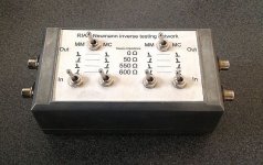
as others already pointed out ... the source impedance should be taken into account.
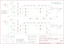
I did exactly that in my own inverseRIAA .... switchable for source impedances of 0R, 50R, 550R and 600R ... as well as 1kHz reference levels of -40dB@600R and -60dB@60R (switch MM/MC) ... see attachments.
Later I designed a smaller and internally shielded SMD version for a fixed 50R source impedance ....since my DAAS32 as well as the QuantAsylum and most other signal generators feature 50R output impedance anyway.
I still find it a very useful device, even though I mostly use the user filter option of the QA.
The QA uses post filtering only and doesn´t allow prefiltering its generator part.
This may generate overload problems or a low signal level depending on the topology and dimensioning of Your Phono stage.
That is where the inverseRIAA shines 😉
jauu
Calvin
as others already pointed out ... the source impedance should be taken into account.
I did exactly that in my own inverseRIAA .... switchable for source impedances of 0R, 50R, 550R and 600R ... as well as 1kHz reference levels of -40dB@600R and -60dB@60R (switch MM/MC) ... see attachments.
Later I designed a smaller and internally shielded SMD version for a fixed 50R source impedance ....since my DAAS32 as well as the QuantAsylum and most other signal generators feature 50R output impedance anyway.
I still find it a very useful device, even though I mostly use the user filter option of the QA.
The QA uses post filtering only and doesn´t allow prefiltering its generator part.
This may generate overload problems or a low signal level depending on the topology and dimensioning of Your Phono stage.
That is where the inverseRIAA shines 😉
jauu
Calvin
Attachments
Is this project available for others to build?
I could use a nice reverse RIAA network.
I could use a nice reverse RIAA network.
I'm currently (and verrrrry lowly) in the process of building a ragtag prototype of the MvdG phono stage and a (better-than-my-1976-possibly-still 1dB ?) reverse RIAA lossy network, or better than is built into a Sound Technology 1200. Intent is to make a Lipshitz/Jung (883K) with 600 Ohm-ish R3. Can I assume (yes, I know) that I could reduce R3 arbitrarily without significant change to the important mid-band inflections?
All good fortune,
Chris
You could reduce R3… but should you?
While mid-band inflections are fairly robust, R3 (in the Lipshitz/Jung network) contributes to both impedance shaping and precise time constants. Shrinking it too much risks underdamping the curve or skewing the slope, especially if the generator’s output impedance is non negligible.
Think of R3 not just as a resistor, but a trusted partner in crime.
Bend him too far, and he’ll mess with your curve behind your back.
Build bravely, but measure often.
All good fortune back at you,
Alan
Alan,
I simulated your circuit in LTSpice, see example below with 70K load on the MM output showing the deviation from an ideal A-Riaa curve.
What comes out is that Rsource should be <= 50R to stay within 0.1dB up to 20Khz.
However, load impedance only affects overall attenuation but not the accuracy to stay within 0.1dB.
Hans
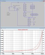
Thanks Hans, that's a really helpful confirmation. I actually ran my own simulations in Multisim as part of finalizing the attenuation structure, and your LTSpice result lines up closely with what I got.
Here’s the simulation side of the passive IRN project from my end:
Once the attenuation structure was finalized, I ran a full frequency response test in Multisim to check how closely the circuit tracks the theoretical inverse RIAA curve, from 20 Hz to 20 kHz. The target was ±0.1 dB, the result came in at ±0.11 dB deviation, consistent across both channels.
The simulated output at 1 kHz landed at –40.08 dB for the MM path. The MC output follows the same curve, just 23 dB lower, as both share the same core network with the split at the output.
Here’s the MM output curve compared with the ideal inverse RIAA. Really happy with how it held up across the full audio band.
Is this project available for others to build?
I could use a nice reverse RIAA network.
Yes, it’s already built, and I’m now sharing the project step-by-step here (design theory, schematic, simulation, build process, etc.).
Once I’ve posted the remaining parts, I’ll also include full documentation, BOM, and Altium files in case you or others would like to build your own version.
Thanks for your input, Drazen, I appreciate your words and the excellent capacitor tip!Hi Alan,
Very nice and neatly executed project, congrats!
Since your are in precision, I can only drop a hint about components choice. For capacitors there are 1% polystyrene extended foil (extended foil means minimal inductance) caps, they are not in production for long time, but can be found, made by RIFA (PFE series) in 80's. Except they need to be found , they are also large, complicated all together but as far as I know the best filter cap ever.
Recently I finished preamp with passive RIAA and achieved max 0.04db mismatch between channels by using those, 0.05% resistors, and where I could not get exact value: hand picked from 2% resistors to reduce number in network.
Here is link showing deviation from left and right channel. I did not measure absolute riaa accuracy, but since components and math are right, there is no need to doubt. PS, in that post I mentioned 0.3db mismatch, think I was tired then, it is one zero more.
https://www.diyaudio.com/community/...ono-preamplifier-thoughts.414816/post-8035424
PS, Few good people here mentioned need of matching input and output impedance's here , IMHO excellent advice to make your tool even more usefull
Best,
Drazen
Those extended-foil polystyrene caps are truly special. For this build, I went with WIMA FKP2s and NISSEI polypropylene film types, mainly for their availability and consistent mechanical construction, but I’ll definitely keep an eye out for the old RIFA PFE series, especially if I go for a future ultra-low-noise version.
And that amazing 0.04 dB result! Really impressive work. 👍
Thank you!Yes, it’s already built, and I’m now sharing the project step-by-step here (design theory, schematic, simulation, build process, etc.).
Once I’ve posted the remaining parts, I’ll also include full documentation, BOM, and Altium files in case you or others would like to build your own version.
Thanks Calvin, really appreciate the detailed explanation and the photos, that’s an impressive setup.Hi,
as others already pointed out ... the source impedance should be taken into account.
I did exactly that in my own inverseRIAA .... switchable for source impedances of 0R, 50R, 550R and 600R ... as well as 1kHz reference levels of -40dB@600R and -60dB@60R (switch MM/MC) ... see attachments.
Later I designed a smaller and internally shielded SMD version for a fixed 50R source impedance ....since my DAAS32 as well as the QuantAsylum and most other signal generators feature 50R output impedance anyway.
I still find it a very useful device, even though I mostly use the user filter option of the QA.
The QA uses post filtering only and doesn´t allow prefiltering its generator part.
This may generate overload problems or a low signal level depending on the topology and dimensioning of Your Phono stage.
That is where the inverseRIAA shines 😉
jauu
Calvin
The switchable source impedance feature is a great idea, especially for testing how different signal generators and phono inputs behave under realistic conditions. I kept mine optimized around 50 Ω, as that’s what many signal generators aim for, but your implementation is clearly much more versatile.
I haven’t worked directly with QuantAsylum gear myself, but I completely agree with your point about the limitations of post-filtering. Without proper analog pre-filtering, it’s easy to run into overload or insufficient drive, exactly why I decided to build this standalone unit.
Thanks again for sharing your approach, very inspiring.
Last edited:
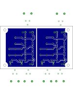
With the schematic and simulations wrapped up, here’s a closer look at the physical build, both the electronic and mechanical sides of the project.
This filter uses separate PCBs for left and right channels (dual mono). While not strictly required, it significantly reduces crosstalk when testing stereo phono stages. Each board sits inside its own aluminum enclosure.
All parts were hand-soldered, and key RC values were selected for tight matching. Polypropylene film capacitors from WIMA and Nissei were used throughout, and all resistors are 1% metal film. To hit target values more precisely, some components were combined in series or parallel, this helped stay within the ±0.11 dB window observed in simulation (post #35).
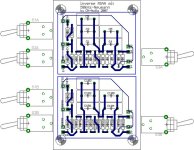
The PCBs were designed in Altium Designer, with a compact layout and fully star-grounded topology. Signal routing was kept short and direct to minimize coupling and maintain channel separation.
Photos below show the boards at various stages — from raw assembly to final enclosure. While dual enclosures weren’t strictly necessary, early measurements showed a clear reduction in inter-channel coupling using this approach.


This filter uses separate PCBs for left and right channels (dual mono). While not strictly required, it significantly reduces crosstalk when testing stereo phono stages. Each board sits inside its own aluminum enclosure.
All parts were hand-soldered, and key RC values were selected for tight matching. Polypropylene film capacitors from WIMA and Nissei were used throughout, and all resistors are 1% metal film. To hit target values more precisely, some components were combined in series or parallel, this helped stay within the ±0.11 dB window observed in simulation (post #35).
The PCBs were designed in Altium Designer, with a compact layout and fully star-grounded topology. Signal routing was kept short and direct to minimize coupling and maintain channel separation.
Photos below show the boards at various stages — from raw assembly to final enclosure. While dual enclosures weren’t strictly necessary, early measurements showed a clear reduction in inter-channel coupling using this approach.
- Home
- Source & Line
- Analogue Source
- Designing a High-Accuracy Passive Inverse RIAA Filter, Why Build One at All?