Friends, I’d really appreciate your help and ideas.
I’m building my first speaker system and learning the theory along the way. The plan is to make a 2-way speaker with a horn. Based on recommendations, I chose the Eminence Deltalite II 2515 and the B&C DE250 for the drivers.
Originally, I built cabinets with a large slot port, but no matter what I tried, the port wouldn’t resonate. Eventually, I blocked it off, thinking it was just too big—even though impedance measurements seemed to show it was doing something. I then installed two round ports instead, thinking that would definitely work. I tried everything—from calculated lengths to extreme ones—but my measurements just don't change. No matter what I do, the graphs stay the same: there’s no bass, and the ports don’t seem to work. It makes no difference—even if I remove the ports entirely. The only time I see a small change is when I completely block the ports.
I feel like I’ve tried every possible configuration. I even consulted an expert who has built multiple high-end systems—he confirmed that the calculations are correct, but we still don’t understand why it’s not working.
I’d be grateful for any advice.
Here are the specs:
Cabinet volume (empty): 87 liters
Internal dimensions: 438×464×432 mm
Ports: two round holes, 70 mm in diameter, facing downward
Driver: Eminence Deltalite II 2515 | 15”
- Nominal Impedance: 8 Ω
- Power Handling: 300 W (600 W program)
- Resonance (Fs): 42 Hz
- Usable Frequency Range: 54 Hz – 3.7 kHz
- Sensitivity: 99.2 dB
- Vas: 204 liters
- Qts: 0.38
- Xmax: 4.8 mm
- Sd: 856.3 cm²
- BL: 15.7 T·m
- Re: 5.29 Ω
- Le: 1.15 mH
- Mms: 72 g
- Cms: 0.2 mm/N
- Vd: 411 cc
Attachments
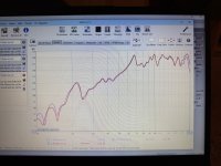


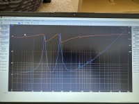
From the measured impedance it should be rolling off in the 30 Hz range. It shows alot of resonances.
From the measure FR my first thot was a leak.
dave
From the measure FR my first thot was a leak.
dave
The two resonant peaks show that the ports are working, tuning at ~ 30Hz, which is too low for that driver

The enclosure is completely sealed — all joints are glued tight. These measurements were taken without any damping material. Adding some damping smooths the frequency response a bit, but doesn’t make a significant difference.From the measured impedance it should be rolling off in the 30 Hz range. It shows alot of resonances.
From the measure FR my first thot was a leak.
dave
Yes, I can see that from the impedance graph — but no matter what I do, or how long I make the ports, the situation only gets worse. The only improvement happens when I completely remove the tubes and just leave open holes. Then the impedance graph looks closer to what I want — but strangely, the frequency response measurements don’t change at all.The two resonant peaks show that the ports are working, tuning at ~ 30Hz, which is too low for that driver
I even tried stuffing the enclosure with sheets of foam to change the internal volume and proportions, but again, it had no effect on the frequency response — it’s like the enclosure isn’t doing anything at all.
What am I doing wrong?
Attachments
Given the impedance changed w/ your port changes & port sealing the issue is most likely with the measurement.
Was the bass audibly different w/ these changes? If so you may want to try separate independent close mic measurements of the woofer & port to eliminate major room influence.
New measurements and or changes to the time windows in the gating of your existing measurements should reveal differences.
Was the bass audibly different w/ these changes? If so you may want to try separate independent close mic measurements of the woofer & port to eliminate major room influence.
New measurements and or changes to the time windows in the gating of your existing measurements should reveal differences.
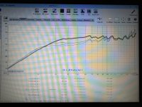
Green = your box with 100 watt input
Yellow, 300 liters tuned to 45 hz, 9 dB more at 50 hz, same 100 watt input. 100w input gets you to xmax in this box.
Yellow, 300 liters tuned to 45 hz, 9 dB more at 50 hz, same 100 watt input. 100w input gets you to xmax in this box.
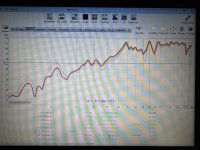
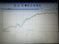
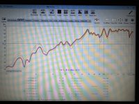
Thanks for the ideas. I took three measurements for each of the three configurations. The first one is with a short port 90 mm long, the second with a 150 mm port, and the third with just an 18 mm port — basically no tubes at all. The results are in the photos. The first photo shows the overall measurement. The second one is the port. The third is the driver.Given the impedance changed w/ your port changes & port sealing the issue is most likely with the measurement.
Was the bass audibly different w/ these changes? If so you may want to try separate independent close mic measurements of the woofer & port to eliminate major room influence.
New measurements and or changes to the time windows in the gating of your existing measurements should reveal differences.
In all the images, the highlighted trace is the one without tubes.
Apologies for the photo quality — I use a separate Windows PC for measurements, and I honestly don’t know how to use it properly.
Attachments

diyuser2010,
I didn’t quite understand. Based on your calculations, are you saying that 87 liters is too small of a volume for this driver?I agree with noggers. Low frequencies are difficult to measure indoors. How far away from the woofer was the microphone when you did your measurements? Did you gate out the low frequencies?
I also don't understand your build. You wrote that your ports are facing down, but i see 2 big ports facing the front. Do your ports open into the horn-like ports on the bottom? If so, those may be adding length to your port.
And then I'm confused by your impedance graph. It shows 2 peaks, indicating a ported enclosure, but you wrote in response to Planet 10 "The enclosure is completely sealed" Are you sure?
As Pete McK pointed out: your tuning is too low for your driver. And diyuser2010 showed that the port is better tuned to 45 Hz (but with 300liters)!
Here is what I would do if I were in your position:
- Recognize that those horn-like openings on the bottom are probably acting as ports or port extensions, and you can't really predict their tuning frequency because of their shape.
- Model your drivers with the cabinet volume your have. If you can find a response curve you like, make port(s) exiting the front (or back, or top, or sides) of your speaker.
- If you can't find a model you like, try models with less internal volume. See what you can come up with. If you find one you like, fill in the volume with blocks of wood or whatever else works.
- When you take measurements, make them close-miked, like noggers recommended. Make separate measurements at the port exits. Try to do it outdoors if you can.
Thanks for your reply. I did the measurements from about a meter and a half away, and also did separate close-mic measurements right at the port and right at the woofer.
The horn-like openings at the bottom are the only thing left to consider. But they’re much larger than the ports themselves, so I’m not sure they have any real effect. These openings are actually leftovers from the original slot port that ran along the bottom and nearly the entire back wall. I completely blocked that off and redirected the ports into the same space, but made them much smaller. The problem is that when I had that huge slot port, the measurements were almost the same. Practically nothing changed.
When I said the enclosure is completely sealed, I meant there are no leaks outside of the ports.
I understand that the tuning is too low according to the impedance graph — but how do I raise it? The only time I see a proper tuning around 42–45 Hz is when I completely remove the tubes and just leave open holes.
I understand that I could drill another hole on the side, front, or back — but before I start ruining the cabinet, I’d like to figure out if there are any other options. What if that doesn’t help either?
- Model your drivers with the cabinet volume your have. If you can find a response curve you like, make port(s) exiting the front (or back, or top, or sides) of your speaker.
- If you can't find a model you like, try models with less internal volume. See what you can come up with. If you find one you like, fill in the volume with blocks of wood or whatever else works.
I’ve already tried simulating different dimensions, and I even reduced the volume and changed the internal shape using foam sheets — but none of that made a difference.
shorten the port or increase the diameter, or a combination of both.but how do I raise it?
That's more evidence that the space below your cabinet is - indeed - acting like a port.The only time I see a proper tuning around 42–45 Hz is when I completely remove the tubes and just leave open holes.
I wonder what would happen if you increased the diameter of those open holes.
Also: How does it sound with the tubes removed?
The highlighted frequency response graph shows the system without the ports. (The smoother line shows the port’s output, while the other graph represents the overall measurement)That's more evidence that the space below your cabinet is - indeed - acting like a port.
I wonder what would happen if you increased the diameter of those open holes.
Also: How does it sound with the tubes removed?
Increasing the diameter would be a pretty drastic step, and I’d rather not go there yet—especially since it’s not easy to reverse once done.
Previously I had a large slot-style port, but it didn’t work either. I assumed it was because the port was too big, so I sealed it off and added round tubes instead.
But again—no real change.
I already tried reducing it to just a single port, but still—it didn’t start working.shorten the port or increase the diameter, or a combination of both.
I even tried placing my hand near the port to feel any air movement, but there was almost nothing.
Attachments
a reflex box must always have damping!
best is like 5cm thick foam fixed / glued to all internal wall sides.
low q drivers can sound bass shy irrespective of port tuning especially if there is no damping inside. Resonances then override / dominate the sound.
Just tune reflex low and if necessary put the box close to back wall or even corner placement for more bass.
Sometimes its difficult to measure the output.
Putting the mic 5cm close to port and then seperately the driver shows contribution of both seperately.
Thanks for the tip.a reflex box must always have damping!
best is like 5cm thick foam fixed / glued to all internal wall sides.
Damping was actually the first thing I did — I bought special denim insulation, about 5 cm thick.
As for the measurements, I already posted them above — they include separate close-mic readings of the port and the driver.
The box is way to small (should be arround double that size) for a tuning arround 45hz with that driver. So without eq (dsp) you won't get there with any port. I would even call for a bigger cabinet (200L with added volume for port, bracing and driver) to be real good. 87L will give you the rsponse (more or less) that you got, with any type or size of port. The cabinet is just too small.
Hi Shakuto,
I'm no expert on speaker technology and I'm fascinated by the knowledgeable answers you've received above, but I'm guessing for what it's worth that your
Just my 2 cents... 🙂
I'm no expert on speaker technology and I'm fascinated by the knowledgeable answers you've received above, but I'm guessing for what it's worth that your
material might be the problem, my bet is that it's overkill.special denim insulation, about 5 cm thick
Just my 2 cents... 🙂
It's worth repeating: Your box is too small of a volume. If...(and only IF) the specs are correct, that driver needs 5.1 cubic feet tuned to 42Hz
Most Eminence drivers I have tested are very close to published specs, but none-the-less, I still test them. The most common variable I have found over the years, is that, the published spec for Vas is wrong. You can use your existing enclosure as a "test box". Learn how to calculate Thiel/Small specs, yourself. This includes testing for Vas. Do not use the added mass method. Use the test volume method, which should actually be more convenient as you already have the box. Bass Reflex yields a really nice sound quality if done correct. Buy yourself a text book on "How to build Loudspeakers" Many are available.
Most Eminence drivers I have tested are very close to published specs, but none-the-less, I still test them. The most common variable I have found over the years, is that, the published spec for Vas is wrong. You can use your existing enclosure as a "test box". Learn how to calculate Thiel/Small specs, yourself. This includes testing for Vas. Do not use the added mass method. Use the test volume method, which should actually be more convenient as you already have the box. Bass Reflex yields a really nice sound quality if done correct. Buy yourself a text book on "How to build Loudspeakers" Many are available.
If you reduce the cross-sectional area of a port while maintaining the same length, you reduce fb.I already tried reducing it to just a single port, but still—it didn’t start working.
I have just simulated the Eminence briefly in WinISD: 87 litres are clearly too small and an fb of 30 Hz clearly too low for this driver. WinISD suggests 160 litres and an fb of 44 Hz as the optimum volume for a QB3 tuning. Of course, it is possible to deviate from this, but not so drastically.
If you really want to tune to 30 Hz, then you should aim for at least 300 litres Vb (as @diyuser2010 already indicated above).
- Home
- Loudspeakers
- Multi-Way
- Help Needed: Bass Reflex Not Working in My First DIY Speaker Build