Hi All,
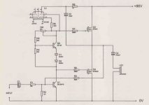
I am currently building the hybrid audio amplifier published in March 2004 issue of Electronics world/ Wireless world. It uses ECC88 Valve , BD139 transistor for thermal feedback/compensation and IRF640/IRF9640 as output MOSFETs. The author has mentioned that potentiometer PR1 is used for output stage quiescent current adjustment. he has also instructed to start the amplifier by tuning the PR1 fully clockwise and then input a low level audio signal, which should be distorted. The PR1 should be then turned counter clockwise slowely until the distortions stop. it should not be turned further. This is quite confusing as the potentiometer can be connected in various methods. My question is that should the potentiometer turned so that it has the highest resistance of 10K to start the amplifier? or it should be started at 0K and then turn to increse the resistor for tuning the quiescent current? Please, refer to the circuit digram in attachment.
I am trying to understand the circuit as it seems that the Valve is biased in grid-leak method, but not sure how the BD 139 functions in this circuit. Also, it seems that the use of valve has to be ECC88 and can not be changed at all with equivalent (such as 6n23P). I am waiting on delivery of some used ECC88 valves and thinking of buying 6N23P NOS ones at some stage if I like the sound of the amplifier.
As the amplifier circuit was fully built, I thought of trying out the 6N6P valve I had at hand in place of ECC88, but I was not sure of the exact value of PR1 10K preset to start the tuning. So, I started with position of max resistance of 10K and supplied a small audio input and swicthed on the amp with the valve heater supply. The amplifier produced good sound (not distorted) for few seconds and then the MOSFETS got shorted and the PCB track got melted along with the feedback resistor showing open. I am now rebuilding it while waiting for the ECC88 valves to arrive and would appreciate some help here from experts as to what should be the starting value of the PR1 so that it would not blow the output MOSFETS when I try to get the amplifier running again this time with ECC88.
Could someone explain the following:
How does the amplifier actually work here with the valves being in grid-leak biase mode as driver?
The most critical question is should the PR1 be max 10K to start with or 0 ohms?
Can I use any substitute valve such as 6N23P as it's hard to get new ECC88/ quite expensive.
The author has provided explanation in the article (March 1004 issue of Electronics World) but, I am not getting how the valve is functioning as driver stage.
Also, is there any other way of tuning the amp than just inputting a low audio signal and using ear for distortions (such as using multimeter/oscilloscope etc.)?
Please, refer to the circuit digram attached, or I can also email you the copy of the article. the magazine is available for free to download on worldradiohistory website.
Thanks in Advance.
Pat
Attachments
Last edited:
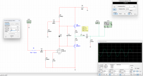
The tube in your schematic is behaving like an PNP transistor that follows lower NPN in signal. I recommend trying something more simple that you understand and you can control with low dificulty. I did something similar like in the picture below in 2018 and used it to drive a power stage that had bias circuit.
Attachments

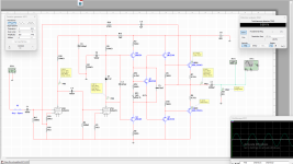
I have made the below design in 30 minutes, you can test it and see if it works, main problem could be the bias not working properly but this situation can be overcome and the second could be tube oscilating but this I belive is less posibile.
Attachments
I think the valve in post #1 is essentially used as a current source.
Regarding the circuit in post 1, I only see potential problems.
56k resistor to drive a feedback node of 12k and 820k ?
Or is it an attenuated feedback loop?
The tube is not supposed to be a driver as far as I can see.
Because of the C2 cap it will have constant voltage between anode and cathode and basically act as a constant current source to Q1 and the functionality would be to set the bias current through Q1 and the bias circuit around Q2.
Viper of potentimeter PR1 should be positioned to the left to give the lowest startup bias current through Q3 and Q4.
Last edited:
The tube is being used as a (not so) constant current source.

The other circuit components and the FET drive requirement imply that it should be about 20mA, but that would only happen if the tube saw 90V and it will see about 1/4 of that. So the CCS will be less than 10mA, maybe not enough?
The pot as shown needs to start at zero Ohms. But this circuit also has the problem that a corroded pot will destroy the FETs. It is a well-known that the pot in a VBE multiplier needs to be in the lower part of the VBE divider so that an open pot just causes cross-over distortion but does not kill the amp. However it must not be the only resistance in the lower side because a zero resistance there would also destroy the amp.
Using a tube as a CCS is a poor excuse to use a tube. There are several better choices. As the tube ages, the current will slowly decrease, and you will have to replace it and/or readjust the bias.
I suggest you use a current limiting series device such as light bulb until you have the amp running properly.
You should understand that this circuit is a novice hack as are so many simple amplifier circuits on the internet. If you want to make a simple amplifier, I suggest you look at the contributions of LV and others here on DIYA. You might also play with the cheap Chinese modules available on Amazon etc.
You should download LT Spice and simulate anything before you build it. There are things that SPICE will not warn you about, but at least it will allow you to understand most of the issues.
Last edited:
Differntial stage is good only for transistor, with tubes because they have no fixed working electric properties they will never work as a miror input stage.
#10 That reasoning requires a better explanation. There are a lot of different solution using tube differental stages.
I would like to hear when you convince Audio Research, Balanced Audio Technology, VAC and some other prominent brands that their input amplifying stages is not working in their preamps. So why would they never work as a mirror (differential) input stage?
What would the technical reason be?
I would not suggest them in this circuit though, since necessary voltage swing and current need to drive the Mosfets will make them distort quite a bit, and since a differential stage by nature mainly have odd order distortion it would be a rather unpleasant edgy tone without listening pleasure.
#8
With the help of the bootstrapping C2 the voltage over the tube is basically equal all the time which will make the tube a pretty good CCS load for the gain stage.
I must say that the more I look at this circuit the more questionable design errors I see.
Leave it...
It's a dead end.
Last edited:
You did not uderstood me, If you make a tube miror input stage and try to couple it directcly to a transistor with no capacitor it will never work. I consider miror stage not important since it is a design created for low distorsion and precision that contradicts with tubes and their role in audio design, you need to preserve tube sound and not destroy it.
You can use tubes differentially , the active VAS transistor is PNP. The cathodes are connected together with the bias resistor to the negative supply. You then need an offset op amp to stabilize the output when the tube is cold.
Than there is another problem even if you manage to get DC offset right you will need reajust over time because of emission degradation.
#12
Sorry, I don't agree with you. But lets not make that a main topic of this thread.
The circuit presented in post #1 are however not a good design in general and should be avoided.
I think a few of us have much better idéas how to do a similar working design if the author have an interest for it.
Dual complementary pairs of Exicon Mosfets would be a good start for output stage.
Drive it with a 10-15mA tube VAS with an output impedance of less than 5k. Parallelled SE E88CC, ECC99, 6CG7, 6FQ7, 12BH7 might be the ticket.
Maybe a cathode follower driving the Mosfets.
Differental tube input stage with a low gain tube like ECC82 or 12AU7. Maybe 6072 if an higher gain integrated amplifier is desired.
Add 6 dB of overall feedback...
That would be a nice start to make a new design around.
Hi Guys,
Thanks a lot to everyone for their responses. I was not expecting so many and so quick responses. I should have asked for DIYA community opinion reg. this amp circuit before going ahead and purchasing all the components.
I was attracted to circuit due to the mystery of the operation of the circuit as the valve used doesnot seems to be in the audio signal path to me (I am not an expert per se.) and used in odd way. The author seemed to know what he is doing as he is using the BD139 for thermal compensation for the output MOSFETs and so on. The article seemed very interesting to begin with. Thanks Tikiroo for putting the link to article here.
But from your responses, it seems that it was complete waste of assembling this amplifier on a general purpose breadboard PCB over the weekend? I am now stuck with all the components as I bought 10 each of these output MOSFETs and have also got a Toroidal transformer. I am still interested in getting this amplifier going just for the sake of hearing the sound quality and until I repurpose components in some other amp circuit.
So, I still have following questions:
Should I wait for the same mentioned tube ECC88 to arrive before giving it a go again? or I should be able to use any other tube such as ECC83, 6N1P or 6N6P by adjusting bias with the PR1 pot?
Should I start with the pot at 0 ohms and then adjust it until the distrortions disappear?
I would really appreciate if you can comnfirm the above.
I am keen on building some good hybrid design as I own few good quality solid state as well as tube amplifiers and each technology has unique sonic character. I am interested in having hybrid as 'Best of both worlds' design, if you will assist me to make one. Design suggested by Flex2 seems quite interesting and I would now download LTspice and try to use it.
Are there any existing good hybrid amplifiers designs on DIYA?
Also out of curiosity, could this Valve CCS part be replaced with something like an FET configured similar to valve such as the lampizator FET-ishitzor design? Just a thought....
Thanks again.
The ECC88 is passing about 6 mA with 40V across it. You could use a 6N6P but the others you mentioned won't pass enough current. Or you could use a depletion mosfet like DN2540, with R6 replaced by a trimpot to set the current.
Eeeeehhh… A quick google search shows that the long-tailed pair differential amplifier was invented in 1936, well before they transistor was invented…Differntial stage is good only for transistor, with tubes because they have no fixed working electric properties they will never work as a miror input stage.
You did not understand what I said at all, read the previous messages. Mirror tube stage will never work with transistors and it is for low THD audio that tubes are not good for, your are just trying to indirectly insult me by claiming I am wrong. Transistors are for mirror stage and this is final, if you want a tube mirror your free to it and prove me wrong, if you did not ask Google you would have not know this.
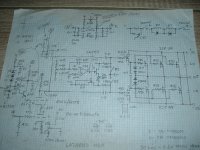
Here's a reverse-engineered, rough schematic of a hybrid amp from the early 90's. It's a Lazarus H1/H1A. Was designed by the late Allen Wright for the Lazarus outfit which existed for a short time in Hollywood, CA. Could be biased for either Class A or AB1. Puts out 50W in class A. Sounds incredible and still holds it's own today. Was VERY favorably reviewed by Peter Moncreif in International Audio Review back then. Understand that Allen never got a nickle/shilling for his efforts.
Lazarus also made a monoblock amp and a preamp - nothing special. H1/A has it's own cult following today - deservedly so!
Lazarus also made a monoblock amp and a preamp - nothing special. H1/A has it's own cult following today - deservedly so!
Attachments
- Home
- Amplifiers
- Solid State
- Electronics World Hybrid Audio Amplifier