https://www.ebay.com/itm/195785024138
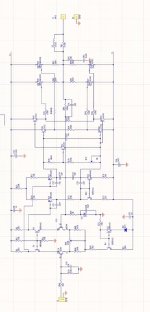
This uses k1058/j162, the circuit diagram looks like a goldmund clone.
But why does this kit have a vbe multiplier? Does it work?
I'm new to vbe multiplier on an amplifier using lateral MOSFET.
In general, sort of. The trail starts with the Hitachi application note circuit: differential input, differential driver, source follower output, then the Maplin exact clone, Maplin like clone and countless hifi and PA clones with various part substitutions, then the Goldmund circuit adding follower drivers and then individual follower drivers and finally the Chinese clones .... well doing their thing on cost saving clone designs (cheaper unmatched part substitutions etc.) that at times don't sound or behave anything like a Goldmund. Some sound really good, others not and some are dangerous. Caveat emptor.
So far, I haven't had any problems with the G29 Hm3s. However, I have made a few modifications. This isn't an amp for beginners. There are other amps that are less difficult. I recommend the Maplin GA28F. It sounds just as good and is significantly cheaper and easier to build. It starts with the fact that the components are easier to acquire than the Goldmund clone.
Attachments
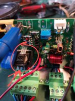

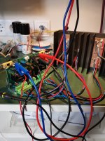
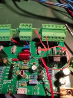
Fundamentally, I don't think the circuit is any worse than the original g29. The VBE also serves as a temperature compensator and counteracts the negative temperature coefficient. That's why the bias transistor is located directly on the large heat sink. I think that's a good idea by the Chinese. However, the savings on components that belong on the board are unfortunate. Probably just to make something cheap. Examples: input capacitor, fuse holder, drivers, the Zobe winding...
Attachments
The Goldmund Wiki contains even more suggestions that would lead to improvements. However, this would require more components to be soldered piggyback to the board.
I definitely consider the Hm3s amp from China to be a Goldmund clone, even though it has a VBE. Although the latter isn't actually a Goldmund one. In my opinion, the secret to a good sound is the double FET at the input. This makes the amp fast and resolving. Finally, it's the numerous lateral MOSFETs that sound excellent and are still very popular today. With six units, the amp is even stable at 2 ohms. The quiescent current is high, and the amp runs in good Class A mode at room volume. What more could you want? Whether a VBE was added or components were replaced... is less important, I think. If you want an original circuit, you should buy an original Goldmund for a few thousand dollars. There will probably only be marginal differences in the sound. Whether the many thousands of dollars are worth it is up to you to decide.
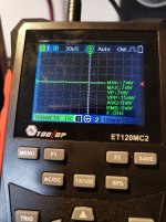
Great work with this circuit, thank you. I experienced the oscilation problems when I used the 2sk135/J50 mosfets. I tried many different compensation techniques, but only the oscilation frequency changed. The sound and oscilliscope measurements are otherwise very good. I am now trying your suggested driver changes. I also found a fault on the PCB with the offset trimpot pin arrangement, which is different to the circuit diagram layout and did not adjust properly. I changed the trimpot pins to connect like in the circuit diagram.
Are you using the Source resistors or did you remove them? What value Gate resistors did you use?
Are you using the Source resistors or did you remove them? What value Gate resistors did you use?
I also considered changing the output driver section to an arrangement like the Spinx Myth 11, which is quite similar. Not sure which would be best yet.
Are you using the Source resistors or did you remove them? What value Gate resistors did you use?
My MOSFETs are selected. However, I used 0.22 ohm source resistors.
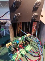
I set the gate resistors to 220 ohms, although 100 ohms worked just fine. They're not located on the board, but directly on the external MOSFETs.
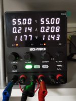
100mA for each output transistor. The power supply shows the current flow of both transistors on each side.Also is your Bias about 200ma per mosfet?
One possible reason why my circuit doesn't oscillate with 2SK135 and 2SJ50 is that I chose all the transistors with a tight tolerance of 1%. For that, I would have to buy several dozen MPSA 42s and MPSA 92s.
Currently, I've made all the modifications suggested in the Goldmund Wiki:
1.
Protection diodes At the base of the driver transistors
2.
I changed the ceramic capacitors from 33p to 4.7p, as in the original circuit diagram.
3.
I swapped the 2sk30 for 2n3958.
4.
I also added a 1uf capacitor in parallel with the 6V Zener diode.
5.
I also added a 1uf diode in parallel with the 470uf capacitor.
The circuit works very well and sounds great.
Last edited:
- Home
- Amplifiers
- Solid State
- Is HM3S a Goldmund clone?