Old brain in need of help.
I just hooked up a new Antek AS2225 and it seems the primaries are out of phase because there's a noticeable hum and it starts to get warm. The secondary voltage seems correct but there's no load connected.
I wired the primaries in parallel, with the two red leads together and the two black leads together. I plan to reverse the leads, but just wondering if I read the diagram wrong or did the manufacturer get the colors wrong?
There are no phasing dots on the transformer's schematic diagram, so it's hard to tell. Seems to me, absent the dots, tying the blacks together and the reds together for 115Vac operation should be the way to go. I'd question the mfr, if that's possible. You might also have a defective, unit, too. An experiment you could try is to energize just one primary winding and read the output voltages. Do the same with just the other primary winding powered. Results should be close to the same using either primary winding. If not, then the transformers has a problem.
Last edited:

Don't reverse the leads red-red, black-black is correct, this will essentially be a dead short across the primary windings since the magnet fields will oppose each other and cancel out basically only the DCR of the winding limits the current. The buzzing and heating may be due to residual DC on your AC line. A DC blocker may be in order.
(I have used a lot of Antek transformers in my own projects)
(I have used a lot of Antek transformers in my own projects)
Last edited:
I would say dim bulb test first. If you do not have a hard short I would have to ask if the noise is from exceeding the primary voltage.
Another way to test would be connect the black primary wires and leave off one of the red primary wires. With power applied do you still get noise? Also is there any real voltage difference between the red wires??
Another way to test would be connect the black primary wires and leave off one of the red primary wires. With power applied do you still get noise? Also is there any real voltage difference between the red wires??
Make sure you don't have a shorted turn.
Confirming what was mentioned previously; leave it as is with red to red and black to black.
Confirming what was mentioned previously; leave it as is with red to red and black to black.
Another way to test would be connect the black primary wires and leave off one of the red primary wires. With power applied do you still get noise? Also is there any real voltage difference between the red wires??
That's a very good proposal. You should get about twice the mains voltage between the red wires if the polarity is wrong and almost zero times the mains voltage when it is correct.
I don't have a DBT but I brought it up slowly with a variac and it was reading about 500mA with no load.A DBT setup should be used.
Both primaries measure 4R and the secondaries measure .3 and .4R. Both secondaries measure 27v.
I hooked it up running only one primary and still it buzzed and got warm. Tried it on the second primary and same result.
I'm going to remove it from the chassis and test again. When I bench tested it I didn't have this problem but I had only hooked up one primary at the time.
It's always good to learn something new. Maybe this is common knowledge, but I learned that surrounding a toroid with a ground is a bad idea.
I thought the small adjacent toroids were creating some competing magnetic fields and causing the problem, but that was not the case. When I disconnected them from the terminal block the problem persisted. But as soon as I removed the terminal block and bracket going across the top, the problem went away.
Go figure.
Attachments
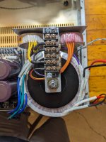
Yes, that makes perfect sense.The bracket is a perfect shorted turn
Good to know you did not buy a busted transformer. Dropping them is also a good way to get a short in an otherwise good transformer. Glad it was a mounting problem.
It's interesting in that the excess current seemed to be in the bolt and bracket, that's where I noticed the most heat. The transformer didn't seem to get warm, so hopefully I didn't damage it.
If you have an inductance meter you can parallel the primaries and read their inductance. If the coils produce opposing magnetising forces in the core, the inductance will drop. If they help each other, the inductance with two parallelled coils should be equal to the inductance with one coil. This assumes the effect of resistance of the coils is insignificant. The reason for obtaining the same inductance as with one coil, is because two coils connected in parallel is similar to using a thicker wire with more cross sectional area.
You can roughly measure the inductance by using a series filament lamp. The effect of the combined inductance will be a dim bulb if the coils aid each other and a fully bright bulb if the coils oppose each other.
You can roughly measure the inductance by using a series filament lamp. The effect of the combined inductance will be a dim bulb if the coils aid each other and a fully bright bulb if the coils oppose each other.
Last edited:
Edit: You appear to have actually created a shorted turn. You need to insulate the bolt or remove the bridge with the terminal strip on top of it. You could also replace the metal strip with a piece of fiberglass PCB material (no copper) - this would be safest long term.I don't have a DBT but I brought it up slowly with a variac and it was reading about 500mA with no load.
Both primaries measure 4R and the secondaries measure .3 and .4R. Both secondaries measure 27v.
I hooked it up running only one primary and still it buzzed and got warm. Tried it on the second primary and same result.
I'm going to remove it from the chassis and test again. When I bench tested it I didn't have this problem but I had only hooked up one primary at the time.
Excitation current with similar transformers IMLE has generally been below 50mA at 120V.
Last edited:
A thick piece of nylon that i could drill and tap might work. Or I just relocate the terminal block elsewhere. It's convenient where it is though.You could also replace the metal strip with a piece of fiberglass PCB material
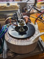
You just made one of these with the mounting hardware. This gun has one loop through the core usually.
Likely your transformer is still good.

Likely your transformer is still good.
I'm reading this while cooking on an induction cooktop 🙂You just made one of these
Attachments

- Home
- Amplifiers
- Power Supplies
- Transformer primaries out of phase?