Greeting all, I'm having trouble planning a circuit with a 0-135v secondary 230ma into a voltage tippler and a tube rectifier. I have never used a doubler or a tippler before
and am a little confused how to wire this up with the tube rectifier. Thanks in advance for your help!
and am a little confused how to wire this up with the tube rectifier. Thanks in advance for your help!
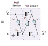
You will need three diodes with isolated heater windings (three GZ34 wired as a single diode or better etc) and follow this simple circuit.
Edit; suggested rectifier added
Edit; suggested rectifier added
Attachments
Last edited:
You should give a bit more info if you expect a response. What do you mean by 'a little confused'?
Schematic of your doubler/tripler (not tippler) and how you intend to do it?
Or do you need help with the basics of a doubler? Or with the specifics of a tube rectifier after a doubler/tripler and its heater wiring?
Note that a doubler or tripler delivers a DC voltage with ripple, just as a regular rectifier, so you should not need the tube rectifier.
A drawing is worth 1000 words.
Jan
Last edited:
Odd-numbered voltage multipliers are the worst for ripple, so a tripler is not good, for all that they were used in colour televisions for the EHT. Also, multipliers are for very low currents only; you do not get something for nothing. They produce a lot of ripple and they have a much higher output resistance than more conventional rectification, so their output voltage collapses when you put a load on them. If that sounds as though I'm trying to put you off, it's because I am. Voltage multipliers make sense when you need kV or when you have negligible current draw (like the polarising voltage on an electrostatic loudspeaker).

Voltage multiplayer is a bad idea for audio, especially with rectifier tubes. He should get a suitable transformer and forget about such ideas.
I think one of the famous Marantz amps used a doubler. Anything above doubling is just silly unless it's for a circuit with insignificant current draw.
I wouldn't consider it a serious option, especially with a tube rectifier.
I think it is a bit of a generalisation to say that a doubler was rarely used, pointing to one implementation. I think they are quite common, and mostly because high voltage electrolytics are hard to come by, especially those able to handle start up voltages where the output tubes need the HT and take a while to warm up.
Tube full wave rectifiers, with multiple heater windings, were also not uncommon in anything commercial where high currents were needed.
I think it could be a 'serious option', depending on the purpose, which was left a bit vague by the OP.
Tube full wave rectifiers, with multiple heater windings, were also not uncommon in anything commercial where high currents were needed.
I think it could be a 'serious option', depending on the purpose, which was left a bit vague by the OP.
The OP was a bit vague of what he wanted exactly but I had the feeling he thought he would need a rectifier after the doubler/tripler.I wouldn't consider it a serious option, especially with a tube rectifier.
With that out of the way, we need to know what voltage he wants out of the doubler/tripler, and the expected current draw.
If that is known a good advice can be given.
Jan
To me it sounds too complicated to multiply the voltage with tube rectifiers. With Si diodes, it's still somehow, but here he needs three rectifier tubes and three separate secondaries for their heating. And I doubt that it is all on that transformer.
No, I believe he thought he needed a tube rectifier after the doubler/tripler.
Didn't realise the doubler/tripler delivered DC (with ripple).
But lets see what he says, I may be wrong.
Jan
Didn't realise the doubler/tripler delivered DC (with ripple).
But lets see what he says, I may be wrong.
Jan
A challenge with any multiplier circuit is as the voltage is multiplied so is the peak and average rectifier current as well as any series resistance.
The peak and average rectifier current multiplies.
The peak and average current carried by the storage capacitors multiplies.
The peak and average current carried by the transformer multiplies.
The series resistance of the storage capacitors multiplies.
The series resistance of any rectifier multiplies.
The transformer series resistance multiplies.
So you get the picture, the total series resistance grows rapidly while at the same time so does the peak current.
Taking a tripler circuit the peak and average current will be at least 3 times higher than in a equivalent non-multiplied circuit and the peak current normally far higher than 3 times higher due to the short conduction angle of the rectifiers.
Add in the effective series resistance is also at least three times higher and you see the loses are now at least 3*3=9 times higher from a non multiplied circuit.
You can see why it quickly becomes difficult to deliver a lot of current from a voltage multiplied circuit.
It is possible to deliver high current in a voltage tripler circuit however you need large low ESR capacitors, high current low loss rectifiers and a low transformer impedance.
The full wave voltage doubler circuit is a pretty good practical limit for higher current applications.
The high peak current and very low rectifier loss requirements will make a tripler a challenge with vacuum tube rectifier due to their limited peak current capabilities and high series resistance.
With your 135v secondary 230ma transformer and using vacuum tube rectification I think you may struggle to deliver even 250 Volts DC @ 50mA current with a tripler circuit and the output ripple will require a good choke to tame. Not so interesting sounding?
Designing voltage multiplied circuits is best done in spice as the results can be unexpectedly poor if enough care is not taken.
I think the smart thing to do here is buy a transformer which gets you the voltage that you need after a solid state doubler.
Use the money that you would have spent on 3x gz34s and 3x 5v filament transformers to buy the correct transformer and use silicon for a squalid state voltage doubler.
A voltage doubler supply is actually really stiff, and tightly regulated without the use of active regulation.
They have the lowest power supply impedance and are a great choice for low distortion tube amplifiers.
Thatis the total opposite of what has been written before.A voltage doubler supply is actually really stiff, and tightly regulated without the use of active regulation.
They have the lowest power supply impedance and are a great choice for low distortion tube amplifiers.
Were they all wrong?
Jan
Just for fun I spiced a tripler using vacuum tubes and a transformer like what was suggested, 135V @230mA or 31VA power.
The first cut I did used a set of three 5U4 and produced less than 300V @50mA.
Not great for all the huge parts and three 5 volt 3A windings needed but better than I expected.
Next I used a set of three 6C10P damper tube that have 6.3v 1.05A filaments, so a lot less power is needed.
These tubes are cheep, tough, low resistance, high peak current and best of all have a 750V voltage rating on the filament to cathode allowing a single 3A heater winding to be used for all three rectifiers.
With this combination I got 46mA DC at 417V output loading the transformer to a equivalent VA of 33, so just a bit over the rated 31VA.
Peak rectifier current is a safe 351mA for a 6C10D tube. Note how high this current is compared to the average 46mA output current!
Not to bad and perhaps even useful if you really, really, really wanted a tripler with vacuum tubes only. LOL
See attached PDF for schematic and spice results.
Attachments
A voltage doubler or full-wave bridge is superior to a full-wave center-tap rectifer, providing about 30% more current from a transformer of the same VA rating (or alternatively, 30% better regulation). That's not including the losses of a vacuum tube rectifier. Of course if efficiency was the only concern, we wouldn't be using vacuum tubes at all.
Comparing the doubler to a full-wave bridge, the doubler has 60 Hz ripple current in the two series capacitors (ESR is slightly higher at 60 Hz). Suppose you have a transformer with two identical secondaries, used in parallel for the doubler, series for the full-wave bridge. Same two filter capacitors in series. Outputs will be identical for voltage, current, ripple voltage and frequency. Of course, the full-wave bridge could use also a single capacitor of half the value, twice the voltage rating.
Comparing the doubler to a full-wave bridge, the doubler has 60 Hz ripple current in the two series capacitors (ESR is slightly higher at 60 Hz). Suppose you have a transformer with two identical secondaries, used in parallel for the doubler, series for the full-wave bridge. Same two filter capacitors in series. Outputs will be identical for voltage, current, ripple voltage and frequency. Of course, the full-wave bridge could use also a single capacitor of half the value, twice the voltage rating.
Opinions vary.Thatis the total opposite of what has been written before.
Were they all wrong?
Jan
Facts, less so.
I don’t have the education to explain it but others do.
McIntosh used them in their mc40s 240s and probably others.
Generally, in my lab, if its good enough for McIntosh its good enough for me.
The above is a key bit.30% better regulation). That's not including the losses of a vacuum tube rectifier
With solid state rectification transformer losses tend to dominate power supply system losses giving the advantage to the doubler or bridge topology as all the copper in the transformer is used on every half cycle for best transformer utilization and lowest losses.
In tube rectification the tube losses are a very important part, in most case the dominant loss of the total power supply system loss.
With vacuum tube rectification tube losses often dominate over transformer losses.
In the full wave center tapped topology the tube rectifiers operate in essence in parallel with the load and in a voltage doubler operate in series with the load.
This means rectifier losses are about 4 times higher in the doubler topology over a center taped topology.
Since tube rectifier losses tend to dominate the power supply system loss, efficiency will be higher with a center tap topology most times when tube are used.
Like most designs questions correct answers are found in the details of the design and simple "good/bad" answers tend to be misleading.
- Home
- Amplifiers
- Tubes / Valves
- Voltage tripler and a tube rectifier