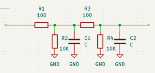
Isn't that a 4th order LP filter. It will remove HF residuals spit out by the DAC and its purpose is to protect any electronics downstream from this HF "garbage". That would be my answer.
//
//
But which will be cut off frequency with 10pF in such filter if we assume it is just a filter? Lets think about multimeter error and it may be 5-20pF, but it measures well 510pF cap right now.
Perhaps this is just trick to show exactly 10K at RCA ?
Perhaps this is just trick to show exactly 10K at RCA ?
Last edited:
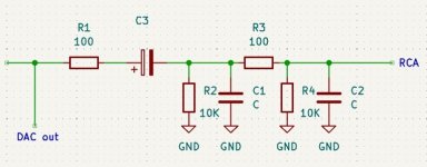
Sorry, my mistake. In original schematics here is additional coupling cap. At the left side here is a circuit to headphones op amp. I use it without coupling caps so show wrong scheme in 1st picture.
Attachments
Last edited:
100ohm and 10nF -> 160k.... Lets await the experts... 🙂 its probably only 2nd order...
http://sim.okawa-denshi.jp/en/CRCRtool.php
//
http://sim.okawa-denshi.jp/en/CRCRtool.php
//
In circuit testing of capacitors often results in wrong values because there are too many other components involved that may disturb measurements. But as pointed out already, the low pass filter is to reduce high frequency garbage from the DAC.
It may also suppress RFI coming from the output.

Looks like C3 is a DC blocking cap with a first pole given by R2 followed by another low pass Pi filter
But will C2 Fo be defined really or is it up to the eternal load? Is the schema complete all the way to the output terminals?
//
//
It’s an anti aliasing filter. All DACs will (and must) have it.
If you think about a digital, time discrete signal, it will look like a series of steps in the time domain. In the frequency domain, that looks like the entire signal is mirrored about the Nyquist frequency (half the sample frequency). This is obviously not good, as it creates a lot of junk signals.
So you need to insert a filter with a cutoff frequency at about half the sample frequency. In the time domain, it looks like smoothing out the steps to form a continuous signal. In he frequency domain, it looks like getting rid of the mirrored spectrum.
What do you mean by "entire signal mirrored" please ?
You meant a band pass filter that is shunted ? I don't understand the phrase...
You meant a band pass filter that is shunted ? I don't understand the phrase...
It’s an anti aliasing filter. All DACs will (and must) have it.
Certainly "must have", but this is not anti-aliasing filter, it's cut-off frequency is too high for this!
This is a RCR circuit to prevent instability of the cable loaded OP, and also a filter of very HF signals, both from the DAC and returned from the cable.
Alex.
Oh, the caps are only 10pF? Well, then I'm at a loss. Are you sure it's not 10nF? That would make more sense.
The frequency spectrum is mirrored. Let's say you have a 44.1kS/s CD signal. It will have useful frequency components up to half that frequency, i.e. 22050Hz. But if you use the output from the DAC, it will actually have a 44.1kHz bandwidth, but anything above 22kHz will be garbage. More specifically, that range will be a mirror image of the useful part of the spectrum. Here's an example. I Sampled a square wave. You can see all its harmonics. But you can also see the same signal mirrored in the upper part of the spectrum.What do you mean by "entire signal mirrored" please ?
Are you sure those caps aren't 10n instead of 10p? Assuming the DAC has some level of oversampling, that would almost perfectly match what I'd expect from an anti-aliasing filter.

It may also suppress RFI coming from the output.
Seems to me this is right point about it.to prevent instability of the cable loaded OP, and also a filter of very HF signals, both from the DAC and returned from the cable.
There is no DC at DAC output, so DC blocking electrolytes to line out are present only for some safety (?) from external DC or mute key burnout protection (?)
yes, this doesn't look like a usual RC-filteronly 10pF
like post #4, only the mute key is not drawn.Is the schema complete all the way to the output terminals?
There could very well be DC on the output of a DAC. Just feed it a string of max level and you have DC. I know, because I accidentally did that once… So if you have a faulty bit stream, you could certainly see DC.
I think this is mistake. At lest 10 times more.Oh, the caps are only 10pF?
I usually use 24R resistors and 100-470pF caps.
Alex.
- Home
- Source & Line
- Digital Line Level
- Please help me understand the purpose of such a filter at DAC line output