First, let me commend to your reading Mark Johnson's excellent article in Linear Audio "Soft Recovery Diodes Lower Transformer Ringing by 10-20X".
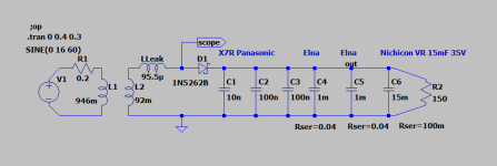
I did a replication of Mark's Test fixture, some of the values are a bit different. (Was a bit puzzled that Figure 3 in the article specified a 1N5262 Zener diode, but I had one and tried it out.)
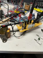
I used an old transformer, probably 1960's vintage, which I was guessing would have high leakage inductance, sure enough it measured 95uH compared to 41uH for an Antek toroid.
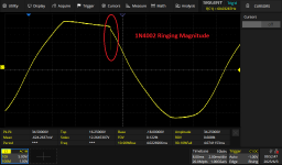
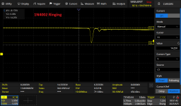
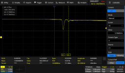
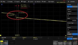
I was expecting the ringing of this transformer's leakage inductance and a 1N4002 diode to be in the 10's of kHz, instead almost 400kHz.
I did a replication of Mark's Test fixture, some of the values are a bit different. (Was a bit puzzled that Figure 3 in the article specified a 1N5262 Zener diode, but I had one and tried it out.)
I used an old transformer, probably 1960's vintage, which I was guessing would have high leakage inductance, sure enough it measured 95uH compared to 41uH for an Antek toroid.
I was expecting the ringing of this transformer's leakage inductance and a 1N4002 diode to be in the 10's of kHz, instead almost 400kHz.
Attachments
That's what it's measuring on the Genrad with the primaries shorted. I'll haul the bugger out to Cleveland where my VNA is resident. I only have the Genrad here.
Drift diodes with step recovery are prone for snappy behavior. For which 1N400X is a perfect example.
P.S. Ringing due to commutation in rectifier is a peculiar signature of ZVS FB converters' generation.
Small saturable inductors (sometimes even heatsunk) as well as "heavy" RC snubbers
(10s of Watts in losses are not unheard of) are usually employed to mitigate the issue.
In mains frequency rectifier it's more of annoyance being an additional noise source.
Perhaps "ideal rectifier" IC/FET combo like LT4322 TEA220X IR11688 will do better?
@jackinnj: A multifrequency measurement is far more reliable and your VNA will give an incontestable answer.
@alexberg: Would you care to elaborate on the physics of drift diodes and their consequent behaviour?
I use Mark Johnson's "Quasimodo" and it's very good, enabling quick determination of snubbers. With the right snubber, even 1N4007 seems fine. Which is nice. And cheap.
@alexberg: Would you care to elaborate on the physics of drift diodes and their consequent behaviour?
I use Mark Johnson's "Quasimodo" and it's very good, enabling quick determination of snubbers. With the right snubber, even 1N4007 seems fine. Which is nice. And cheap.
I would agree on that. An ultimate snubber is usually (quasi)resonant mode of operation.With the right snubber, even 1N4007 seems fine.
In regard to drift diodes. AFAIK it only applies to older slow Si rectifiers. Do not ask me why - I'm no way semi specialist.
Please correct me if I'm wrong (too well seasoned), there's concentration gradient along the "base" of a diode due to a limited mobility. It's usually drawn like trapezoid converting into a triangle. Once the concentration becomes zero at one end, current stops rather suddenly.
I don't have the Linear Audio issue at hand right now, but when I remember it wright he used a variac between wall socket and transformer to make up for shifts in line voltage. It was a point of discussion when the article was published. Do you see a difference between a set up with and without a variac? Does it influence the ringing?I did a replication of Mark's Test fixture, some of the values are a bit different. (Was a bit puzzled that Figure 3 in the article specified a 1N5262 Zener diode, but I had one and tried it out.)
I also used a "variac" -- in an Eico 1078 which is fused and has meters to read current and voltage. Should have no bearing on the results. It was set such that the output voltage was 15 VDC and current 100mA. I believe Variac is a Genrad trade-marked auto-transformer, but haven't taken apart the Eico to see if it is GenRad.
I misread the number, off by a factor of 10!That's a very small leakage inductance for an EI transformer.
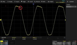
Easy mistake to make. Was the oscilloscope in peak detect mode both times? Nice to see the overshoot/ringing produced without the artificiality introduced by the Quasimodo; there are those who dispute that it occurs at all.
Yes Mark's test rig is somewhat 'special', as it forces a high peak current level due to n.ω.C.RL value of ~ 916 (for n=1, ω=377, C=16,200uF, RL=150Ω), although the transformer effective resistance was not identified. Such a special test condition generates a substantial transient voltage on the sole secondary winding, which being only half-wave rectified, forces a measurable ringing current through the diode junction, to an extent influenced mainly by the diode’s junction capacitance.
I tested a rather large vintage PT for valve amps (400-0-400V 180mA, 6V3 4A CT, 6V3 2.5A CT, 5V 3A, Ferguson PF1067) - it's half-secondary leakage inductance was 7mH.
I tested a rather large vintage PT for valve amps (400-0-400V 180mA, 6V3 4A CT, 6V3 2.5A CT, 5V 3A, Ferguson PF1067) - it's half-secondary leakage inductance was 7mH.
Last edited:
Great catch of a typo more than ten years old! That's a record, a new high water mark, in my experience. Ten years! {manuscript first draft submitted to Jan/L.A. on 15 March 2015}
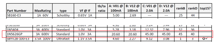
I apologize for the mistake in the caption of Figure 3 and in the tenth row of Table I. I carelessly transposed digits in the part number! Oops! Congratulations to @jackinnj for detecting the error.
At least I got the specifications of the diode correct; as the table states, it is a Silicon diode rated 3 amps and 600 volts. But its correct part number is 1N5626 (datasheet attached) , whereas I typed 1N5262 . And that incorrect part number happens to be a Zener diode, as Jack noted. Mea culpa.
I included some truly excellent diodes in the tests, thus I was going to need a very sensitive test fixture in order to view differences among them. Quite small differences in fact. So my fixture applies a very high peak diode current, and it also uses transformers whose leakage inductance was in the top 10% of leakage inductance among the candidate pool. Big current and big inductance let you observe differences in ringing behavior, even among the best of the best diodes. Because the exact same fixture was used for all diodes, any difference in ringing behavior was solely due to the difference in diodes.
(Why else did you think the fixture includes so many parallel capacitors with such ridiculously low ESR values?)
In my personal view, a Quasimodo derived snubber is cheap insurance. It uses very inexpensive* and easy to source components, it does no harm, and it does some good. Cost is tiny, benefit is possibly large, easy decision. Plus, as @6L6 stated in his talk and live demonstration at BAF-2024, quite a few diyAudio members used Quasimodo as aexcuse reason to purchase their very first oscilloscope. More scopes in the hands of more DIYers, is a good thing. Also, don't underestimate the appeal of a "No-Math" approach to snubbing. A sizeable proportion of DIYers have no confidence in their math skills, and greatly prefer dialing a potentiometer instead of punching buttons on a calculator or spreadsheet. How many times have you read Forum posts "I just want to confirm that to get 15V output, I should set R2=2.7K ohms?" Long before Quasimodo there was Hagerman's article (the first Reference in the Quasimodo design note), but to snub Hagerman's way you need to do some algebra. Which a sizeable proportion of folks choose not to even attempt.
*Unless it's a high voltage secondary, in which case 0.15uF film capacitors begin to become a little spendy.
I apologize for the mistake in the caption of Figure 3 and in the tenth row of Table I. I carelessly transposed digits in the part number! Oops! Congratulations to @jackinnj for detecting the error.
At least I got the specifications of the diode correct; as the table states, it is a Silicon diode rated 3 amps and 600 volts. But its correct part number is 1N5626 (datasheet attached) , whereas I typed 1N5262 . And that incorrect part number happens to be a Zener diode, as Jack noted. Mea culpa.
I included some truly excellent diodes in the tests, thus I was going to need a very sensitive test fixture in order to view differences among them. Quite small differences in fact. So my fixture applies a very high peak diode current, and it also uses transformers whose leakage inductance was in the top 10% of leakage inductance among the candidate pool. Big current and big inductance let you observe differences in ringing behavior, even among the best of the best diodes. Because the exact same fixture was used for all diodes, any difference in ringing behavior was solely due to the difference in diodes.
(Why else did you think the fixture includes so many parallel capacitors with such ridiculously low ESR values?)
In my personal view, a Quasimodo derived snubber is cheap insurance. It uses very inexpensive* and easy to source components, it does no harm, and it does some good. Cost is tiny, benefit is possibly large, easy decision. Plus, as @6L6 stated in his talk and live demonstration at BAF-2024, quite a few diyAudio members used Quasimodo as a
*Unless it's a high voltage secondary, in which case 0.15uF film capacitors begin to become a little spendy.
Attachments
Last edited:

... with such ridiculously low ESR values and such ridiculously high ripple current ratings ...
I only caught the typo as I wondered "Why would Mark use a Zener in this application?". In any event, the Zener didn't blow up when I tried it, I happened to have the numeric in the zener drawer!
I wonder if the inter-winding capacitance doesn't swamp the diode junction capacitance -- after viewing the leakage inductance on the VNA and seeing that it is pretty flat with frequency, it would seem that the tens of puffs Cjo doesn't satisfy f= 1/(2pi sqrt (LC))
I wonder if the inter-winding capacitance doesn't swamp the diode junction capacitance -- after viewing the leakage inductance on the VNA and seeing that it is pretty flat with frequency, it would seem that the tens of puffs Cjo doesn't satisfy f= 1/(2pi sqrt (LC))
If your equipment is able to plot impedance vs frequency, you can characterize the "leakage inductor" 's self-inductance, self-resonant frequency, and self-capacitance. From that plot,
- |Z| = 2 * pi * f * Lself . . . . . . . . well below the S.R.F.
- |Z| = 1 / (2 * pi * f * Cself) . . . . well above the S.R.F.
Example of impedance plot of leakage inductance of PF1067 from post #12. Equivalent inductance was pretty constant from low freq up to 'inductive' region (80 deg phase) circa 30kHz, after which reality may start to bite with probing and compensation for my soundcard.
With a 1N4007 rectifier, a spectrum plot of the HT ac waveform showed a 60kHz minor peak that was 100dB below the fundamental mains voltage. Adding a 470pF across each half-HT reduced the minor resonance to 50kHz. Changing to a UF4007 pushed a just discernible resonance down in to the now lower weeds. The diode turn off current slope for this test was about ~ 0.30mA/us, so the bell wasn't being hit very hard for this setup. Quasimodo indicated a 1nF//9.4nF+1k5 snubber was appropriate.

With a 1N4007 rectifier, a spectrum plot of the HT ac waveform showed a 60kHz minor peak that was 100dB below the fundamental mains voltage. Adding a 470pF across each half-HT reduced the minor resonance to 50kHz. Changing to a UF4007 pushed a just discernible resonance down in to the now lower weeds. The diode turn off current slope for this test was about ~ 0.30mA/us, so the bell wasn't being hit very hard for this setup. Quasimodo indicated a 1nF//9.4nF+1k5 snubber was appropriate.
I have seen different self-resonant frequencies between two halves of a push-pull output transformer where the windings weren't balanced. Older mains transformers often wound centre-tapped windings in a similar way, with half the winding wound, centre tap brought out, then the other half winding wound on top. More recent transformers tend to use bifilar windings, so a 2 x 15V transformer configured as 15-0-15 would have near-identical windings and near-identical resonant frequencies.It is rumored that EI core inductors and transformers often exhibit multiple self resonant frequencies; you could find out whether yours does or doesn't.
- Home
- Amplifiers
- Power Supplies
- More snubber musings