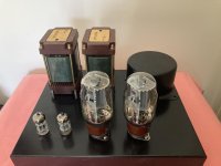
This project was inspired by the now obsolete AirTight M101 Kitset Single Ended KT88 that used Tamura Output transformers , my findings may differ from your take on it or even the parameters I am using , as always safety is paramount with amplifies like this with lethal voltages involved .
https://positive-feedback.com/nos/a...ss impact was very,could have a killer system.
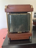
First output transformers tried were the Muse Coils I have, 4.6K , %40 UL or Triode tap or 3.3K /2.25K triode rated at 1.6T @ 25Hz I am very happy with its 2kg mass / chassis footprint 65Wx90Dx120H mm and performance so was good start for this Amplifier , which may develop further.
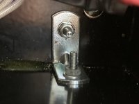
The bog standard chassis from Hammond I used was the Mouser Part Number ,1444-12123 chassis and 2 x 1434-1212 bottom plates used , only problem is the Hammond aluminium chassis are only 1mm thick and had to order two bottom plates , cut one bottom plate in half ,file to size and glue the extra piece under the chassis using a decent glue ie Loctite 480 Instant Adhesive , then 4 x steel brackets bolted in each corner underneath and one each side midway for strength to hold transformer weight , a messy and slow process . Note only the rear half of the chassis was strengthened to 2mm in total for support .
Will likely get a local sheet metal shop to fold a 2mm aluminium chassis and have drop through holes for a hammond 290LX power transformer , tube sockets holes , Tamura output transformer holes and IEC rear punched out in future .
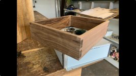
The wooden surround to fit around the Hammond Chassis is Tasmanian Blackwood and Oak for the rear , so stamped speaker / RCA/Power lettering is clearly visible , there is more work to do with further miter cuts to curve corners and flat sections will also be curved inwards .
Once the wooden surround is bolted to the Hammond chassis it will also strengthen the sides considerably .
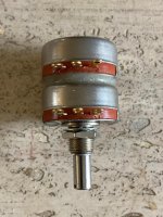
A cutout for the volume control knob at the front will be made for the 100K PEC Carbon Precision series KK/2RV7 potentiometer ,
the best I could find , much more natural sound than plastic film in the signal path IMHO .
https://www.digikey.com.au/en/produ...4m3MbB8DDerkn2rs4tywuTUwLPRRIB-j3JuTna9Tw5iNw
A KT66 will first fitted a tried , drawing below in triode mode , followed by the KT88/6550.
Biasing the KT66 ( B+ 385v ) and KT88/6550 ( B+ 400v ) will take a bit of trial and error as each set of tubes often don't operate near enough to published curves , again a 10 ohm resistor in series with the tubes cathode resistor to get it spot on and output transformers soak up a few more volts than others depending on current required
This project is being shared as a personnel build not a DIY guide as your own designs may well be better .
I saw a number of pictures on the net including under the Chassis of the M101 , quite a simple affair of 12AX7 plates strapped together 1.1mA approx and a KT88 biased with a 600ohm cathode resistor 70mA ? starting with the premise of a B+ rail close to 400v DC .
It looked as though the 12AX7 input tube with plates / grids and cathodes strapped together looked to be biased near 1.1mA , mine is now 1.4mA on latest amended version 3 drawing on post below , please ignore drawing on post 5 and bias @ 2mA is incorrect , trouble trying to reverse engineer from old photos , lesson learned always check current with 10 ohm resistor in series . The main dropper from B+ to the 12AX7/12AD7 is 68K !! not 6.8K typo on the KT88/6550 so ignore drawing on post 5 & 8 please .
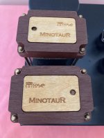
With the latest Muse Coils ( Model MinotauR OTSE - 060NHY-046 ) 1.6T @ 25Hz custom design for me a primary of 4.6K / 3.3K /2.25K / - 4 / 9 and 16 Ohms with %40 Ultra Linear tap for the 4.6K , an ideal set of transformers to use on type 45 , 2A3 KT66, KT88 ( max 8 watts ) and type 50 , 70mA at 4.6K and 80mA at 3.3K / with a %40 UL tap or simply run as Triode !
The Muse Coils are very well made and sound as good as they look , the correct timbre across all types of music is very apparent , excellent frequency extension and solid bass .
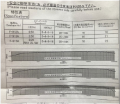
I have a new set of 5K Tamura F915 / 12watts / 70mA / 25Hz -65 kHz with a %40 UL tap output transformers to emulate the " Tamura" sound of the original kitset that I will try next.
I ordered my F915 from SUN AUDIO in Japan , https://www2.big.or.jp/~sunaudio/chumon_e.html they are the agents in Japan and will ship internationally unlike AKIHABARA .
Sun Audio's stock list is a bit out of date but they do have Tamura Single Ended , F912 2.5K F913 3.5K and F915 5K UL in stock , better price than ebay .
The latest Tamura specs and curves are below in my images .
In triode mode the KT66 sound had excellent transparency , full and extended bass and high frequencies , the midrange had all the qualities of a 2A3 but nearly twice the power at 5.8 watts .
The overall impression was excellent with Muse Coils transformer's ( https://musecoils.com/?bot_test=1) , Single HiB cut C / Double Coil.
In Ultra Linear at 7.2 watts the KT66 exhibited more bass slam and high frequency dominance , the midrange was neutral but to match the 2A3 I will remove the Jupiter Copper Foil capacitor and replace with a Toshin DUCT Paper in Oil Vita Q capacitor from the Hifi Collective UK to get more of the AM101 original sound .
Now I have installed a GE KT88 / 6550 although labelled GE KT88 it looks certainly to be a 6550 which is a highly regarded NOS GE tube .
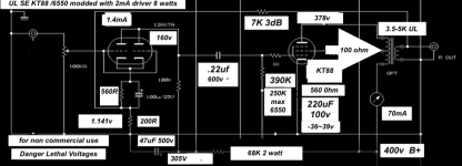
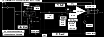
With 400v B+ my take on the M101 with 12AX7 driver circuit enclosed but remember tube current on the KT88 /6550 can often vary to published curves so always put a 10 ohm 2 watt resistor in series with the cathode resistor to ground and measure volts to ground V = IR you should see 0.7v ( 70mA ) on the lowest setting on your volt meter , somewhat abbreviated . So often the cathode resistor will need too trimmed a little for the desired current .
The 12AD7 I used , same 12AX7 with tighter specs also needed to be trimmed for cathode resistor value , using a 10 ohm resistor to check current .
The sound of the SE6550 in Ultra Linear was very nice indeed , the synergy between the 12AX7 and 6550 produced excellent bass and high frequency extension and the midrange was surprisingly smooth and sweet , I have introduced about 3dB of CFB as this seems the break point where the sound stage closes in a bit , with a Mundorf Silver Supreme capacitor detail was excellent but sound stage pushed forward .
This amplifier has far less distortion than a SE300B at 6-8 watts I have previously built with more dynamics and bass impact , I suspect the SS Hexfreds power supply can attribute a little to this phenomenon
A Toshin DUCT paper VitaQ oil was installed and the soundstage moved further back between my speakers and after more running in will post more findings .
The Problem with the now Vintage AT- M101 kit set is the old carbon resistors and electrolytic's will need swapping out now for longer term reliability , quite a lot of work .
The 12AX7 I decided to use was a NOS Japanese Toshiba 12AD7 the very low noise closely matched version the the 12AX7 with very close matched plates suitable for strapping together .
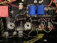
All my signal wiring is point to point copper foil at present and resistors I have chosen are mainly Amtram AMRG & AMRT carbon resistors and capacitors from mainly Vishay Sprague ATOM and a full bridge rectifier using HEXFREDs bypassed with 0.01 uf 1200v ceramic capacitors .
The LM317HV has been replaced with wire wound resistors .
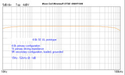
NOW are few pictures of the chassis and woodwork ( almost finished ) to be fitted and Muse Coil Transformer Plots 15Hz - 52Khz -1dB 1K driving impedance.
This information is for general interest only and you would need to come up with your own designs for any build and be suitably qualified in what ever country or State you live in to embark on building these projects as inlet power supply involving 110,120,230,240v AC mains voltage and DC voltages in this range can be lethal .ie B+ 400 v
https://positive-feedback.com/nos/a...ss impact was very,could have a killer system.
First output transformers tried were the Muse Coils I have, 4.6K , %40 UL or Triode tap or 3.3K /2.25K triode rated at 1.6T @ 25Hz I am very happy with its 2kg mass / chassis footprint 65Wx90Dx120H mm and performance so was good start for this Amplifier , which may develop further.
The bog standard chassis from Hammond I used was the Mouser Part Number ,1444-12123 chassis and 2 x 1434-1212 bottom plates used , only problem is the Hammond aluminium chassis are only 1mm thick and had to order two bottom plates , cut one bottom plate in half ,file to size and glue the extra piece under the chassis using a decent glue ie Loctite 480 Instant Adhesive , then 4 x steel brackets bolted in each corner underneath and one each side midway for strength to hold transformer weight , a messy and slow process . Note only the rear half of the chassis was strengthened to 2mm in total for support .
Will likely get a local sheet metal shop to fold a 2mm aluminium chassis and have drop through holes for a hammond 290LX power transformer , tube sockets holes , Tamura output transformer holes and IEC rear punched out in future .
The wooden surround to fit around the Hammond Chassis is Tasmanian Blackwood and Oak for the rear , so stamped speaker / RCA/Power lettering is clearly visible , there is more work to do with further miter cuts to curve corners and flat sections will also be curved inwards .
Once the wooden surround is bolted to the Hammond chassis it will also strengthen the sides considerably .
A cutout for the volume control knob at the front will be made for the 100K PEC Carbon Precision series KK/2RV7 potentiometer ,
the best I could find , much more natural sound than plastic film in the signal path IMHO .
https://www.digikey.com.au/en/produ...4m3MbB8DDerkn2rs4tywuTUwLPRRIB-j3JuTna9Tw5iNw
A KT66 will first fitted a tried , drawing below in triode mode , followed by the KT88/6550.
Biasing the KT66 ( B+ 385v ) and KT88/6550 ( B+ 400v ) will take a bit of trial and error as each set of tubes often don't operate near enough to published curves , again a 10 ohm resistor in series with the tubes cathode resistor to get it spot on and output transformers soak up a few more volts than others depending on current required
This project is being shared as a personnel build not a DIY guide as your own designs may well be better .
I saw a number of pictures on the net including under the Chassis of the M101 , quite a simple affair of 12AX7 plates strapped together 1.1mA approx and a KT88 biased with a 600ohm cathode resistor 70mA ? starting with the premise of a B+ rail close to 400v DC .
It looked as though the 12AX7 input tube with plates / grids and cathodes strapped together looked to be biased near 1.1mA , mine is now 1.4mA on latest amended version 3 drawing on post below , please ignore drawing on post 5 and bias @ 2mA is incorrect , trouble trying to reverse engineer from old photos , lesson learned always check current with 10 ohm resistor in series . The main dropper from B+ to the 12AX7/12AD7 is 68K !! not 6.8K typo on the KT88/6550 so ignore drawing on post 5 & 8 please .
With the latest Muse Coils ( Model MinotauR OTSE - 060NHY-046 ) 1.6T @ 25Hz custom design for me a primary of 4.6K / 3.3K /2.25K / - 4 / 9 and 16 Ohms with %40 Ultra Linear tap for the 4.6K , an ideal set of transformers to use on type 45 , 2A3 KT66, KT88 ( max 8 watts ) and type 50 , 70mA at 4.6K and 80mA at 3.3K / with a %40 UL tap or simply run as Triode !
The Muse Coils are very well made and sound as good as they look , the correct timbre across all types of music is very apparent , excellent frequency extension and solid bass .
I have a new set of 5K Tamura F915 / 12watts / 70mA / 25Hz -65 kHz with a %40 UL tap output transformers to emulate the " Tamura" sound of the original kitset that I will try next.
I ordered my F915 from SUN AUDIO in Japan , https://www2.big.or.jp/~sunaudio/chumon_e.html they are the agents in Japan and will ship internationally unlike AKIHABARA .
Sun Audio's stock list is a bit out of date but they do have Tamura Single Ended , F912 2.5K F913 3.5K and F915 5K UL in stock , better price than ebay .
The latest Tamura specs and curves are below in my images .
In triode mode the KT66 sound had excellent transparency , full and extended bass and high frequencies , the midrange had all the qualities of a 2A3 but nearly twice the power at 5.8 watts .
The overall impression was excellent with Muse Coils transformer's ( https://musecoils.com/?bot_test=1) , Single HiB cut C / Double Coil.
In Ultra Linear at 7.2 watts the KT66 exhibited more bass slam and high frequency dominance , the midrange was neutral but to match the 2A3 I will remove the Jupiter Copper Foil capacitor and replace with a Toshin DUCT Paper in Oil Vita Q capacitor from the Hifi Collective UK to get more of the AM101 original sound .
Now I have installed a GE KT88 / 6550 although labelled GE KT88 it looks certainly to be a 6550 which is a highly regarded NOS GE tube .
With 400v B+ my take on the M101 with 12AX7 driver circuit enclosed but remember tube current on the KT88 /6550 can often vary to published curves so always put a 10 ohm 2 watt resistor in series with the cathode resistor to ground and measure volts to ground V = IR you should see 0.7v ( 70mA ) on the lowest setting on your volt meter , somewhat abbreviated . So often the cathode resistor will need too trimmed a little for the desired current .
The 12AD7 I used , same 12AX7 with tighter specs also needed to be trimmed for cathode resistor value , using a 10 ohm resistor to check current .
The sound of the SE6550 in Ultra Linear was very nice indeed , the synergy between the 12AX7 and 6550 produced excellent bass and high frequency extension and the midrange was surprisingly smooth and sweet , I have introduced about 3dB of CFB as this seems the break point where the sound stage closes in a bit , with a Mundorf Silver Supreme capacitor detail was excellent but sound stage pushed forward .
This amplifier has far less distortion than a SE300B at 6-8 watts I have previously built with more dynamics and bass impact , I suspect the SS Hexfreds power supply can attribute a little to this phenomenon
A Toshin DUCT paper VitaQ oil was installed and the soundstage moved further back between my speakers and after more running in will post more findings .
The Problem with the now Vintage AT- M101 kit set is the old carbon resistors and electrolytic's will need swapping out now for longer term reliability , quite a lot of work .
The 12AX7 I decided to use was a NOS Japanese Toshiba 12AD7 the very low noise closely matched version the the 12AX7 with very close matched plates suitable for strapping together .
All my signal wiring is point to point copper foil at present and resistors I have chosen are mainly Amtram AMRG & AMRT carbon resistors and capacitors from mainly Vishay Sprague ATOM and a full bridge rectifier using HEXFREDs bypassed with 0.01 uf 1200v ceramic capacitors .
The LM317HV has been replaced with wire wound resistors .
NOW are few pictures of the chassis and woodwork ( almost finished ) to be fitted and Muse Coil Transformer Plots 15Hz - 52Khz -1dB 1K driving impedance.
This information is for general interest only and you would need to come up with your own designs for any build and be suitably qualified in what ever country or State you live in to embark on building these projects as inlet power supply involving 110,120,230,240v AC mains voltage and DC voltages in this range can be lethal .ie B+ 400 v
Attachments
-
 Muse1.jpg32.6 KB · Views: 135
 -
 Under chasiis .jpg97.4 KB · Views: 133
 -
 Muse Coil Freq Resp.png49.8 KB · Views: 134
 -
 Wood Chassis.jpg85.2 KB · Views: 121
 -
 wood chassis 2.jpg77.5 KB · Views: 115
 -
 Muse3.jpg50.9 KB · Views: 126
 -
 Muse2.jpg35.7 KB · Views: 121
 -
 400v-305v.png15.9 KB · Views: 29
 -
 12AX7 .jpg119.1 KB · Views: 29
 -
 12AX7 bias v .jpg121.3 KB · Views: 41
 -
 SE K88 UL : 12AX7 version 3.png124.2 KB · Views: 43
 -
 KT66 Triode mode.png151.5 KB · Views: 20
 -
 Brackets x 4 .jpg90.1 KB · Views: 16
 -
 Tamura 915.png546.8 KB · Views: 10
 -
 PEC2.jpg99.6 KB · Views: 5
 -
 PEC.jpg127.2 KB · Views: 5
Last edited:
Hi, Am moving house so test gear and lost's of excess parts being boxed up , seeing it a 1K load on the test i expect 20Hz at -1dB easily and still well into the 40KHz range -1dB on the HF side .
Alexander at Muse Coils oversizes his C cores and very thorough in the manufacturing design phase .
The KT66 in triode mode is very linear indeed .
Alexander at Muse Coils oversizes his C cores and very thorough in the manufacturing design phase .
The KT66 in triode mode is very linear indeed .
Attachments


Sounds encouraging, and the transformers look beautiful. But it would be interesting to see actual measurements when you are able.
SE KT88/6550 indeed are GE6550 tubes ! for my AirTight M101 inspired design .
After installing these tubes and biasing them to 70mA 560 ohm R was time to see what I thought of this design based around a 12AX7 plates strapped together , mine set to 2mA and bias -1.5 giving enough headroom for about 3dB of cathode feedback .
I also installed a pair of Mundorf MCap-Supreme capacitors 0.22uF / 1000v as the power rail ramps up over 400v until the tubes warm up .
The sound in Ultra Linear is rather nice , smooth very dynamic with excellent frequency balance bass mids and high frequency .
The solid state Hexfreds with Vishay Sprague Atom capacitors and a Lundahl smoothing choke work well together.
My 12AD7 low noise close matched version of the 12AX7 certainly works well at 2mA and the synergy is very nice indeed with the GE6550.
This amp has more drive and punch than the SE300B I have built with both Tamura and Hashimoto output transformers , even with Western Electric 300B installed the SE6550 has better dynamics and bottom end in my system .
The mids are smoother and fuller than expected with the 6550 and when the Tochin DUCT Vita Q paper and oil arrive I will install them for the more Vintage sound of the 90's era and earlier around the M101's inception .
Next will be the wiring up of the Tamura 5K ultra linear transformer to more closely match the old design .
After that a Mu Follower 5670 to be fitted instead of the 12AD7 as more current drive would be better for both triode mode of the KT66 and KT88/6550 .
My schematic is included for reference only and note the 6550 cathode resistor often needs trimming dependant on each brand's operation .
70mA is really just to keep the output tubes current in check as the Tamura F915 is limited in this regard .
Please not voltages and current were set for my power transformer and may vary depending how much current headroom it has for a Hexfred set of bridge diode rectification driven by a secondary 200ma / 300v AC or 300 -0- 300 AC for full wave diode's with final output can be trimmed with a zener on the centra tap to ground is my method .
Just a reminder the schematic is for reference only , you will need to come up with your own design and need to be a suitably qualified person in your country to build amplifiers with lethal voltages !
Attachments


Last edited:
With the values of the cathode resistors and plate resistor of the 12AX7 (or 12AD7), the stated current of 2 mA does not match with the stated bias of 1.5 V. The 2 mA would cause a bias of about to 2.4 V over the resistance in the cathode lead (1K + 220 Ohm).
But looking at the Va/Ia curves for 12AX7/12AD7, the plate current per triode section at a bias of about 2.4 V and a plate voltage of about 190 V would be less than 0.1 mA.
So I think there is something wrong with one or more values in your schematic.
Perhaps the 1K in the cathode lead should be 500 Ohm? With 500 Ohm things look OK to me.
Hi,
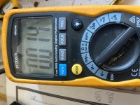
I measured the current over a 10 ohm resistor and got 1.2mA for 1200 ohm for the existing drawing 190V plate 1.5V bias
replacing the 1K resistor with a 560 ohm + 200R got me 1.4mA current and bias of 1.141v and a plate voltage of 156V so will adjust the drawing as I need a little headroom for drive level for a 6550 the KT66 is easier to drive but want to be able to use both in this amp with a switch to change bias resistors .
A LM317HV set to 70mA on the output tube cathode may be another option I will try as its easier to bias this way .
Changed drawing for the SE UL KT88 /6550 with new resistor values for 1.4mA 12AX7 / 12AD7 with 6.8K dropper from the 400v B+ and voltage changes .
Thanks Robert ,always measure the cathode voltage across a 10 ohm resistor in series resistor the main cathode resistor to ground , please ignore drawing on post 5 as 2mA on 12AD7 / 12AX7 was incorrect , correct drawing version 3 below and now on original post 1.
Thanks Robert ,always measure the cathode voltage across a 10 ohm resistor in series resistor the main cathode resistor to ground , please ignore drawing on post 5 as 2mA on 12AD7 / 12AX7 was incorrect , correct drawing version 3 below and now on original post 1.
Attachments

Last edited:
I think that the value of the 6.8K resistor in combination with the voltage drop of 95 V over it cannot be correct. With these values the current through it would be I = V / R = 95 / 6800 = 0.014 A, so 14 mA. But the drivers of the two channels only pass 1.4 mA each, so 2.8 mA in total.
Besides the above: When looking at the Ia/Va curves for the 12AX7/12AD7, the plate current per triode section at a plate voltage of about 155 V and a control grid voltage of about -1.14 V is about 1 mA. So, the two sections together would pass about 2 mA, which is quit some more than the 1.4 mA as stated in your schematic.
Besides the above: When looking at the Ia/Va curves for the 12AX7/12AD7, the plate current per triode section at a plate voltage of about 155 V and a control grid voltage of about -1.14 V is about 1 mA. So, the two sections together would pass about 2 mA, which is quit some more than the 1.4 mA as stated in your schematic.
The two 1/2 of the triode in a single tube are strapped so each half draws 0.7mA x2 = 1.4mA
The two channels have separate power rails . 68K typo dropping resistor .
I find published curves don't always match up with each individual tube and across a 10 ohm resistor in series with the cathode resistors of 760ohm I measure 0.014mV and total bias voltage of 1.141v . so my readings are correct for this tube in my amp
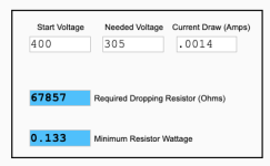
I have inserted the volt meter readings on my original post above and also the 400v-305v calculation @ 1.4mA draw.
The original post drawing is amended .
The two channels have separate power rails . 68K typo dropping resistor .
I find published curves don't always match up with each individual tube and across a 10 ohm resistor in series with the cathode resistors of 760ohm I measure 0.014mV and total bias voltage of 1.141v . so my readings are correct for this tube in my amp
I have inserted the volt meter readings on my original post above and also the 400v-305v calculation @ 1.4mA draw.
The original post drawing is amended .
Last edited:
"I find published curves don't always match up with each individual tube" is so true. It should be used as a guide, not a bible.
I had a poster on audiokarma endlessly harass me over there (they eventually were banned) based off his calculations eventually claiming "You have no idea what you are talking about" as I tried to explain that I'm measuring the as built amp with a known good volt meter (actually checked it with 3 different quality meters) and this is the voltage reading.
It's the same with performance testing, if I'm testing/measuring an as built amp, that is a more accurate test than a computer sim is.

Of course!that is a more accurate test than a computer sim is.
It is real world.
Walter
The only tube I found that performed exactly to spec and published curves was a brand new set of Western Electric 300B .
The GE black plate 5670 I have are the next adventure as they are the original frame grid more close to the 6922 except different pin out , allowing higher voltages than a 6DJ8 / ECC88.
Will try SRPP then a Mu follower GE 5670 to swap out the 12AX7 12AD7 as it see how this sounds in this amp .
The original AirTight M101 had some rave reviews so will also try the new Tamura F915 in this amp but its limited to 70mA and 8 watts will be achievable .
Naysayers will say the old Tamura are way better than the new but I have an old set of Tamura tried in different designs and built a 300B with new Tamura F913 and preferred it to the Hashimoto H20-3.5U tried with the SE300b , just my view and everyone has their own take on output transformers.
The Hashimoto H203S with a SE2A3 had nice mids and top end but the bottom octave was MIA
 FYI, we do not take kindly to our members bringing fights and troubles from other forums over to this one. If you pay attention, you will have seen this mentioned before. Leave off-forum disputes off of our forum.
Grid01@ do you know what kind of core does the Tamura F913 use? C-Core? How much DC resistance? Thanks.The only tube I found that performed exactly to spec and published curves was a brand new set of Western Electric 300B .
The GE black plate 5670 I have are the next adventure as they are the original frame grid more close to the 6922 except different pin out , allowing higher voltages than a 6DJ8 / ECC88.
Will try SRPP then a Mu follower GE 5670 to swap out the 12AX7 12AD7 as it see how this sounds in this amp .
The original AirTight M101 had some rave reviews so will also try the new Tamura F915 in this amp but its limited to 70mA and 8 watts will be achievable .
Naysayers will say the old Tamura are way better than the new but I have an old set of Tamura tried in different designs and built a 300B with new Tamura F913 and preferred it to the Hashimoto H20-3.5U tried with the SE300b , just my view and everyone has their own take on output transformers.
The Hashimoto H203S with a SE2A3 had nice mids and top end but the bottom octave was MIA
Hi, I suspect the F913 are EI core the only one of the new addition to be C core is the F2007A ( formally F2007 but new case now ) and probably a single cut C core double bobbin like the Muse Coils I am currently using .
I don't remember the DCR of the F913 but normally a drop of 10 -12 volts across the primary depending on current used .
The EI core tend to be warmer in the mid range for me , I don't get to hung up about C or EI cores , although I favour the single Cut C core double bobbin.
I do have a set of 5K double C core Permalloy 50 and pure Silver Wire primary / secondary metal sourced from Japan , for a type 50 .
https://frank.pocnet.net/sheets/049/5/50.pdf
Ongaku use the Perma 50 and Silver Wire but the 211 runs at 1000v DC + and don't need 20 plus watts so never ventured there .
I still have a brand new set of Silver Coil Lowther PM2A Alnico magnets brand new in their boxes if I ever get around to building a cabinets for them .
.
Last edited:
The transformers weren't oversized as I wished them to be, if I recall correctly, there was a footprint limitation. The compromise was designing them at 1.6T for full power at 25Hz, where I usually aim for 1.3T-1.4T for GOSS. Anyway, I'm happy that the project is getting successful. The tonality of the transformers comes from the materials they're built of, this is the trademark of the Minotaur series. I also aim for a maximum copper content vs core mass.
- Home
- Amplifiers
- Tubes / Valves
- Single Ended KT66 / KT88 6550 Triode Strapped & Ultra Linear