Greetings, Friends. I've long wanted to build a simple headphone amp using the Soviet 6N6P double triode as output. Seeing the earlier post of a Morgan Jones 6DJ8 Headphone Amp - style build completed with 3x 6N1P tubes inspired me to whip up a schematic for a similar circuit.

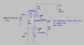
Adapted from the Optimized Morgan Jones Headphone Amplifier circuit. R4 & R5 prob need to be adjusted to equalize voltages across each triode. Not sure about bypass caps.
Power Supply, expected voltages in Blue:

Most of the power supply designs from the original Headwize page feature CRC filters for the HT and a cap to float the LV. I'd rather use a traditional voltage divider to elevate the heater supply about 72v. Will this work as drawn? Do I need a cap somewhere in there?
Any advice on the subject welcome, thanks for taking a look!
w
Adapted from the Optimized Morgan Jones Headphone Amplifier circuit. R4 & R5 prob need to be adjusted to equalize voltages across each triode. Not sure about bypass caps.
Power Supply, expected voltages in Blue:
Most of the power supply designs from the original Headwize page feature CRC filters for the HT and a cap to float the LV. I'd rather use a traditional voltage divider to elevate the heater supply about 72v. Will this work as drawn? Do I need a cap somewhere in there?
Any advice on the subject welcome, thanks for taking a look!
w
Attachments

Last edited:
My recommendation would be not to use a single lamp in preamplification. Use one for each separate channel, so half of each.
6N1P is a double triode, one bottle can do both channels for preamplification.
Or did you have something else in mind?
Or did you have something else in mind?
I know it's dual triode. When I played with this project, I also made the version that I recommended to you. You will have a pleasant surprise...
The project is easy to do on the work table.
The project is easy to do on the work table.
How do you do this if I may ask? Do you just leave half the preamp tube unused or do you use both halves for the single channel the way the power tube does?I know it's dual triode. When I played with this project, I also made the version that I recommended to you. You will have a pleasant surprise...
The project is easy to do on the work table.
Why?Leave half the preamp tube unused.... You will have a pleasant surprise...
And what is that pleasant surprise?
Similar here from kodabmx, not exactly the same though.
Just an FYI for those who asked... I now have a board for 9AJ as input (6N1P 6DJ8 6CG7 etc) instead of 6N3...
Same question as artosalo: Why?Hi,
Leave half the preamp tube unused.
I assume you think about the risk of crosstalk between the two channels. But the 6N1P has a shield (connected to pin 9) between the two triode sections. So, with proper lay-out, the amount of cross-talk at audio frequencies will be negligible.
Not everyone connects pin 9 where it should.
Even so, there is a noticeable difference when listening.
Even so, there is a noticeable difference when listening.
Dubadub, you didn't specify what impedance 'phones you plan to use. This type of circuit might not do to well with low impedance, low efficiency 'phones. Think planars, or some low imp. dynamics. 366 volts B+ sounds a bit high. You might need to put a cap across the 68K, 3W resistor in the PS to minimize hum. A 280 volt AC, bridge rectified, secondary might made more DC than you want or need.
🤣🤣🤣🤣🤣🤣Which side of twin triode is better?
Does it vary between different types?

- Home
- Amplifiers
- Tubes / Valves
- An Idea for a 6N1P-6N6P / 6H1∏-6H6∏ OTL Headphone Amp