Design Phase - 35Hz Tapped Horn w/ Compression Chamber (Hog Scoop + Inverted Driver)
This project has been inspired by all the love for Hog Scoops... And the fair share of hate they get as well.
This will bee my first attempt at an 18" horn subwoofer.
Proposed plan is based on the well known "Hog Scoop",
a tried and tested free design hosted over on the freespeakerplans.com forum.
https://www.freespeakerplans.com/?view=article&id=31:hog-scoop
Drawn up nearly 20 years ago, this well proven classic has stood the test of time and is a very
clever piece of speaker box design, still to this day.
Credit for this creation must go to Stipe Ercegovic, more commonly known a Staiper, a well respected member on the Speakerplans Scoop subforum for a long time,
but he disappearred from there several years ago and doesn't seem to frequent these places anymore.
The Hog Scoop, technically an F1 hybrid of sorts, the offspring of two genetically similar species,
living a life somewhere between a tapped horn and a traditional back loaded "scoop".
A rear loaded horn with the bonus of the driver shooting into the horn path, or a tapped horn enclosure
equipped with a compression chamber.... Call it what you will, this quarter wave resonator is well capable of
hitting the low bass notes and producing high SPL when equipped with the right hardware.
So, I would like to run inverted drivers in a slightly tweaked version of this enclosure, something similar to the image attached to the end of this post.
These are the M4.18 subwoofers, made by MM-Acoustics in Europe, a Macedonian outfit headed by Marjan Milosevic, a regular poster and long time member over on SP.
My god, they look absolutely amazing, so business like.
This is the look I am going for.... They are absolutely badass indeed.
Anyway..... enough airy introductions, and down to business then !!
Hog Scoop Hornresp input parameters
First things first, I decided it would bee prudent to simulate a hog scoop with a driver in it's normal orientation first..... Cone side out.
This was to bee my baseline sim, a benchmark to work from before l went tweaking the original design.
And staight away I ran into problems.
For a start, the speakerplans.com forum isn't very active these days..... And a huge amount of information from back when it was is just lost.
Many externally hosted images are not there any more, there are many dead links, hosted plans, you name it, gone !!!
It didn't make my research easy but I did what I could with what I had.
That said, there were many helpful and informative threads to bee found amongst all the bickericking and the politics in the Scoop subforum.
So, lets discuss what was available to find on the net first.... Multiple posts regarding the Hog Scoop hornresp input parameters were scattered around the web....
And just not consistent.
I was hoping to pull some numbers out of a post or a sketch somewhere but straight off the bat, numbers and posts were conflicting.
Unfortunately, I found more than one set of digits, which only infuriated and confused me even more.
Here are the most posted (and reposted) HR Hog Scoop numbers, I beleive they orignally came from Staiper, and these ones were the most common to bee found online,
copy and pasted in at least 4 different places, so I am inclined to stick with the guy who originally penned the Hog Scoop design. He did create it after all.
Stipe Hog Scoop
S1 = 750
Con = 112.8
S2 = 1062
Con = 42
S3 = 1770
Con = 51
S4 = 2544
Con = 47
S5 = 5700
Vrc = 0
Lrc = 0
Fr = 0
Tal = 0
Vtc = 49456
Atc = 86
Re-posted by bitzo,
https://forum.speakerplans.com/forum_posts.asp?TID=16974&PID=214119&title=database-simulation#214119
toastyghost,
https://forum.speakerplans.com/forum_posts.asp?TID=16974&PID=727583&title=database-simulation#727583
Bee,
https://forum.speakerplans.com/forum_posts.asp?TID=72607&PID=828911&title=hog-scoop-drivers#828911
and salzburgsound system
Here you go!
Regards, Ben
The hog scoop is 950mm x 986mm x 636mm
The hornresp numbers:
s1=750
con=112.8
s2=1062
con=42
s3=1770
con=51
s4=2544
con=47
s5=5700
vrc=0
lrc=0
fr=0
tal=0
vtc=49456
atc=86
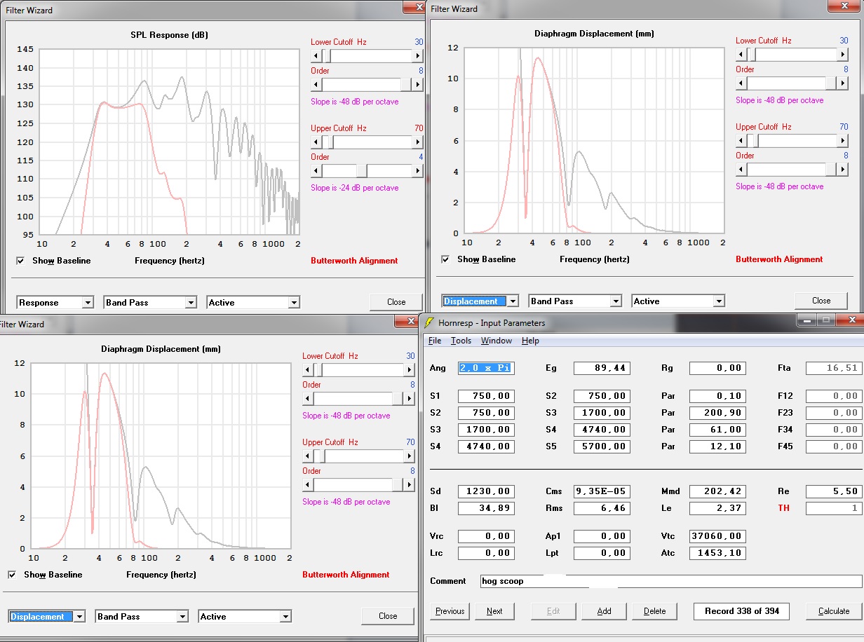
The next set of input data numbers to bee found were these ones you see below.....
--------S1 = 750
Par = 0.10
S2 = 750
Par = 200.90
S3 = 1700
Par = 61.00
S4 = 4740
Par = 12.10
S5 = 5700
Vrc = 0
Ap1 = 0
Lrc = 0
Lpt = 0
Vtc = 37060
Atc = 1453.10
Posted by Heathrow B Line
https://forum.speakerplans.com/foru...=901195&title=scoop-hr-reference-guide#901195
epa
Freddi
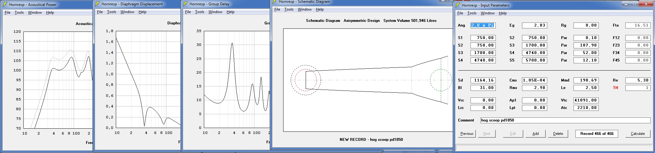
And one more, with newer and revised numbers, taken from a post by user "epa" from 2014.
S1 = 750
Par = 0.10
S2 = 750
Par = 187.90
S3 = 1700
Par = 52.00
S4 = 4740
Par = 12.10
S5 = 5700
Vrc = 0
Lrc = 0
Ap1 = 0
Lpt = 0
Vtc = 41091
Atc = 2210.00
Posted by epa
Other than these three sets of input parameters, I did find a few posts by Staiper himself, modeling the Hog Scoop as an exponential horn,
in quite a numerically sparce fashion I must add.... It would seem this stripped down form of modelling came from Rog Mogale himself.
i will link after the following
---------->
Staiper Exponential Hog
S1 = 750
S2 = 5700
L = 260 EXP
Vtc = 36000 (with driver)
Atc = 1000
https://forum.speakerplans.com/forum_posts.asp?TID=8887&PID=218876&title=hog-scoop#218876
Staiper Exponential Again....
S1 = 750
S2 = 5700
L = 257 EXP
Vtc = 37000
Atc = 9000
https://forum.speakerplans.com/forum_posts.asp?TID=8329&PID=77534&title=tapped-horn-design#77534
And finally....... An attempt at simming a Hog Scoop by the man, Rog Mogale himself.
S1 = 750
S2 = 5700
L = 240 EXP
Vtc = 35000
Atc = 890
https://forum.speakerplans.com/forum_posts.asp?TID=8329&PID=77097&title=tapped-horn-design#77097
And here is a good thread full of interesting tit bits where Rog discusses his exponential scoop modelling methods with others.
https://forum.speakerplans.com/forum_posts.asp?TID=8329&PID=77097&title=tapped-horn-design#77097
A must read for anyone into this line of work.
Annd..... Time to take stock.
All my research and reading paid off, but unfortunately I still feel I do not have any concrete numbers for a Hog Scoop simulation binge.
So, I took some time out and drew up a scaled plan of the Hog, just enough to play with.
it gave me a much more definite idea of the direction I asm going in, speaker boxes ofthen quite literally build themselves as the project goes on.
Solutions are often just so obvious when you have the material object taking shape before your eyes.
And measurements can bee taken from the plan and scaled up to something that resembles real world numbers.
(Drawing attached)
And just to bee sure, I am going to get my hands on one side panel first, (18mm sheet board 986 x 950mm) and draw it out @ a life size scale on the floor.
Drivers for this design
I currently have 2 B&C 18TBX100 (4 ohm) belonging to a friend to use for the first 2 boxes and am debating which drivers to buy for the rest.
Quite likely B&C as well, I like the power handling (1500w) and price of the 18SW1OO.
When given the option, I usually buy 4 ohm versions of any driver when I can.
They can often bee had for the same price as their 8ohm equivalents but sometimes not. Sometimes they are just more hassle to obtain but I do make an effort to
use 4 ohm drivers when ever I can.
I am also open to other brands, I do know I need a certain type of driver to do well in these boxes and if one particular driver turns out to bee
especially suited to the task it will surely bee strongly considered.
So far, everything is going well.... The only other uncertainty I have right now is the design of the rear chamber.
I am not sure exactly how it will end up but I am confident the design (and build) process will answer it's own questions if and when they arise.
More on that in detail later.
Okay, I think I have written enough for now.... Any advice and criticism is warmly welcomed.
Please feel free to join me on my journey of discovery and don't bee shy to interject or comment if need bee.


This project has been inspired by all the love for Hog Scoops... And the fair share of hate they get as well.
This will bee my first attempt at an 18" horn subwoofer.
Proposed plan is based on the well known "Hog Scoop",
a tried and tested free design hosted over on the freespeakerplans.com forum.
https://www.freespeakerplans.com/?view=article&id=31:hog-scoop
Drawn up nearly 20 years ago, this well proven classic has stood the test of time and is a very
clever piece of speaker box design, still to this day.
Credit for this creation must go to Stipe Ercegovic, more commonly known a Staiper, a well respected member on the Speakerplans Scoop subforum for a long time,
but he disappearred from there several years ago and doesn't seem to frequent these places anymore.
The Hog Scoop, technically an F1 hybrid of sorts, the offspring of two genetically similar species,
living a life somewhere between a tapped horn and a traditional back loaded "scoop".
A rear loaded horn with the bonus of the driver shooting into the horn path, or a tapped horn enclosure
equipped with a compression chamber.... Call it what you will, this quarter wave resonator is well capable of
hitting the low bass notes and producing high SPL when equipped with the right hardware.
So, I would like to run inverted drivers in a slightly tweaked version of this enclosure, something similar to the image attached to the end of this post.
These are the M4.18 subwoofers, made by MM-Acoustics in Europe, a Macedonian outfit headed by Marjan Milosevic, a regular poster and long time member over on SP.
My god, they look absolutely amazing, so business like.
This is the look I am going for.... They are absolutely badass indeed.
Anyway..... enough airy introductions, and down to business then !!
Hog Scoop Hornresp input parameters
First things first, I decided it would bee prudent to simulate a hog scoop with a driver in it's normal orientation first..... Cone side out.
This was to bee my baseline sim, a benchmark to work from before l went tweaking the original design.
And staight away I ran into problems.
For a start, the speakerplans.com forum isn't very active these days..... And a huge amount of information from back when it was is just lost.
Many externally hosted images are not there any more, there are many dead links, hosted plans, you name it, gone !!!
It didn't make my research easy but I did what I could with what I had.
That said, there were many helpful and informative threads to bee found amongst all the bickericking and the politics in the Scoop subforum.
So, lets discuss what was available to find on the net first.... Multiple posts regarding the Hog Scoop hornresp input parameters were scattered around the web....
And just not consistent.
I was hoping to pull some numbers out of a post or a sketch somewhere but straight off the bat, numbers and posts were conflicting.
Unfortunately, I found more than one set of digits, which only infuriated and confused me even more.
Here are the most posted (and reposted) HR Hog Scoop numbers, I beleive they orignally came from Staiper, and these ones were the most common to bee found online,
copy and pasted in at least 4 different places, so I am inclined to stick with the guy who originally penned the Hog Scoop design. He did create it after all.
Stipe Hog Scoop
S1 = 750
Con = 112.8
S2 = 1062
Con = 42
S3 = 1770
Con = 51
S4 = 2544
Con = 47
S5 = 5700
Vrc = 0
Lrc = 0
Fr = 0
Tal = 0
Vtc = 49456
Atc = 86
Re-posted by bitzo,
https://forum.speakerplans.com/forum_posts.asp?TID=16974&PID=214119&title=database-simulation#214119
toastyghost,
https://forum.speakerplans.com/forum_posts.asp?TID=16974&PID=727583&title=database-simulation#727583
Bee,
https://forum.speakerplans.com/forum_posts.asp?TID=72607&PID=828911&title=hog-scoop-drivers#828911
and salzburgsound system
What is the size of the ”hog scoop”?
How much louder is the hog scoop than the Keystone with the same voltage applied?
Art
Here you go!
Regards, Ben
The hog scoop is 950mm x 986mm x 636mm
The hornresp numbers:
s1=750
con=112.8
s2=1062
con=42
s3=1770
con=51
s4=2544
con=47
s5=5700
vrc=0
lrc=0
fr=0
tal=0
vtc=49456
atc=86
The next set of input data numbers to bee found were these ones you see below.....
--------S1 = 750
Par = 0.10
S2 = 750
Par = 200.90
S3 = 1700
Par = 61.00
S4 = 4740
Par = 12.10
S5 = 5700
Vrc = 0
Ap1 = 0
Lrc = 0
Lpt = 0
Vtc = 37060
Atc = 1453.10
Posted by Heathrow B Line
https://forum.speakerplans.com/foru...=901195&title=scoop-hr-reference-guide#901195
epa
Freddi
the speaker described in your input screen has a "short" 1.25 meter path. With the speed of sound ~343M/s its quarter wave is 343/(1.25*4) ~69Hz.
Below is the input for an 18" driver hog scoop and its path is roughly twice of your input
Can you post a drawing or link to a drawing of the cabinet you want to examine with hornresp ?
Below is the input for an 18" driver hog scoop and its path is roughly twice of your input
Can you post a drawing or link to a drawing of the cabinet you want to examine with hornresp ?
And one more, with newer and revised numbers, taken from a post by user "epa" from 2014.
S1 = 750
Par = 0.10
S2 = 750
Par = 187.90
S3 = 1700
Par = 52.00
S4 = 4740
Par = 12.10
S5 = 5700
Vrc = 0
Lrc = 0
Ap1 = 0
Lpt = 0
Vtc = 41091
Atc = 2210.00
Posted by epa
here is an example of a hog scoop
hog scoop is sort of th .
if you want to go lower you can go the "othorn th"
or design something for yourself (with help of diy)
bottom line is if you want to get low hard,you need a big cab and big driver with big x-max.
hog scoop is sort of th .
if you want to go lower you can go the "othorn th"
or design something for yourself (with help of diy)
bottom line is if you want to get low hard,you need a big cab and big driver with big x-max.
Other than these three sets of input parameters, I did find a few posts by Staiper himself, modeling the Hog Scoop as an exponential horn,
in quite a numerically sparce fashion I must add.... It would seem this stripped down form of modelling came from Rog Mogale himself.
i will link after the following
---------->
Staiper Exponential Hog
S1 = 750
S2 = 5700
L = 260 EXP
Vtc = 36000 (with driver)
Atc = 1000
https://forum.speakerplans.com/forum_posts.asp?TID=8887&PID=218876&title=hog-scoop#218876
Staiper Exponential Again....
S1 = 750
S2 = 5700
L = 257 EXP
Vtc = 37000
Atc = 9000
https://forum.speakerplans.com/forum_posts.asp?TID=8329&PID=77534&title=tapped-horn-design#77534
And finally....... An attempt at simming a Hog Scoop by the man, Rog Mogale himself.
S1 = 750
S2 = 5700
L = 240 EXP
Vtc = 35000
Atc = 890
https://forum.speakerplans.com/forum_posts.asp?TID=8329&PID=77097&title=tapped-horn-design#77097
And here is a good thread full of interesting tit bits where Rog discusses his exponential scoop modelling methods with others.
https://forum.speakerplans.com/forum_posts.asp?TID=8329&PID=77097&title=tapped-horn-design#77097
A must read for anyone into this line of work.
Annd..... Time to take stock.
All my research and reading paid off, but unfortunately I still feel I do not have any concrete numbers for a Hog Scoop simulation binge.
So, I took some time out and drew up a scaled plan of the Hog, just enough to play with.
it gave me a much more definite idea of the direction I asm going in, speaker boxes ofthen quite literally build themselves as the project goes on.
Solutions are often just so obvious when you have the material object taking shape before your eyes.
And measurements can bee taken from the plan and scaled up to something that resembles real world numbers.
(Drawing attached)
And just to bee sure, I am going to get my hands on one side panel first, (18mm sheet board 986 x 950mm) and draw it out @ a life size scale on the floor.
Drivers for this design
I currently have 2 B&C 18TBX100 (4 ohm) belonging to a friend to use for the first 2 boxes and am debating which drivers to buy for the rest.
Quite likely B&C as well, I like the power handling (1500w) and price of the 18SW1OO.
When given the option, I usually buy 4 ohm versions of any driver when I can.
They can often bee had for the same price as their 8ohm equivalents but sometimes not. Sometimes they are just more hassle to obtain but I do make an effort to
use 4 ohm drivers when ever I can.
I am also open to other brands, I do know I need a certain type of driver to do well in these boxes and if one particular driver turns out to bee
especially suited to the task it will surely bee strongly considered.
So far, everything is going well.... The only other uncertainty I have right now is the design of the rear chamber.
I am not sure exactly how it will end up but I am confident the design (and build) process will answer it's own questions if and when they arise.
More on that in detail later.
Okay, I think I have written enough for now.... Any advice and criticism is warmly welcomed.
Please feel free to join me on my journey of discovery and don't bee shy to interject or comment if need bee.
Last edited by a moderator:

Databee,And measurements can bee taken from the plan and scaled up to something that resembles real world numbers.
(Drawing attached)
And just to bee sure, I am going to get my hands on one side panel first, (18mm sheet board 986 x 950mm) and draw it out @ a life size scale on the floor.
Your "Monster Front Loaded BR Sub" was ~160 liters.
The Hog scoop extended to mount the driver magnet out will be over 600 liters, about four times the size (volume) of your "Monster Front Loaded BR Sub".
How much more will it weigh?
Hello Art,
Always good to see you.
The Monster Front Loaded BR Sub is very nearly complete.
The box size needed more port than I had anticipated and it ended up best with no curve port at all, only a flat floor slot rectangle port.
Impedence sweep is almost perfect (equal spikes).
Just ran out to the workshop for a quick and dirty measure.
Monster BR external size is 800 x 700 x 600 Thats 336 litres external volume
The port is about 550 x 180 x 675 somewhere in or around 67 litres.
And the "box" itself is touching around 250 litres internal I do believe, something like that.
By the end of it all I was very happy with it's sound..... And I learned a lot doing it.
Back to the Hog w/ inverted driver.
It will have 4 castor wheels and 8 handles for starters.
Yeah, the Hog tapped horn design is far from final that's for sure.
The extension you mention, which is actually only 50mm might not even make the final cut..... Maybe 25mm.... Maybe no extension at all.
Or matbe I can make the box smaller somewhere else to compensate for the extra volume.
Without it, horn length is about 248cm..... That's somewhere near 34.5Hz
All my messing with bass reflex enclosures (this is my first horn) has led me to think that I like my subs tuned a little high.
I will trade a few low bass notes for a handful of decibels any day of the week.
I also like that drier, spanky sound that a (slightly) higher tuning gives and am not really a fan of a wooly or a boomy bass.
The lower tuning sound also turns into mud and distortion much quicker than the same challenge given to a box of say 40Hz.
Yes, bass reflex has thought me well...... I really do like my SPL's at "war volume".
Maybe I will shorten the Hog horn another bit, ever so slightly, or make other changes that promote pushing the tuning a touch higher.
This design is still fluid.
I still have to get my head around Hornresp properly..... but I will more than likely go in the direction of a shorter horn, smaller rear chamber and a tighter throat
These mods will raise the tuning, a little and squeeze the bandwidth for more SPL too.
I might yet even change the design of the rear chamber completely.
I do not like an 18" hole firing into a 600 x 100 rectangular letterbox.
Maybe there is a more elegant way to couple the driver with the horn but for now it is getting much thought.
Thank you.
Last edited:
Any new info on your development? I am also a fan of the hog scoop and have thought about enlarging it to try to extend the lower frequencies.
Hello Sn95,
Happy to see your appearance here, fellow Hog affectionado's are always welcome.
I have spent the last week researching, studying and playing with Hornresp.
The learning curve is steep, the information load is huge and l would like to check in and post my design phase progress.
After some thinking I have decided a more definiate design criteria for this project.
i will surely sacrifice low Hertz for loudness.
Maximum SPL from 40 to 80 Hz is the target for this horn build while keeping xmax at sensible amounts of travel.
I have developed the habit of doing every simuation twice, the first time round in half space (2 x Pi), flat plane (sub on the ground
in the middle of a field and @ 1W/1M, 2.83v
i also like to run an extra sim, modelling them them as l would use them in the real world.
always, up against as wall and with at as much power input as I can get away with.
With this design I am shooting for about 140dB+ of sensitivity, box size is second in importance.
I suppose I have to ask.... What is the best way to model this enclosure properly.....?
A tapped horn I presume but it is also a back loaded horn of sorts.
i have attached a plot comparison of two sims, both the same hog scoop, the first modelled as a tapped horn and the second as an ND normal horn.
seeing as they are a mix of the two, I feel something can bee learned from this.
One thing that very much interests me is the tuning of the box dimensions to extract as much SPL as possible from the drivers.
i will elaborate more on this later but for now, a few concepts are in need of discussion.
The length of the horn in relation to how the response graph moves around and where I want my cut off.
I read in one thread that as a general rule of thumb, tapped horns seem to perform best when the driver resonance is approximately
twice the tuning frequency of the horn..... in some cases driver fs runs ~1/2 octave above horn cutoff.
In a lot of my recent simming, exponential horn flare cut off frequency (F12) is about 20Hz and my drivers fs is 30Hz.
This sounds good, no....?
And something else.... If I am after max SPL from 40 to 80Hz, and need to raise box impedence, is it okay shorten the horn for more efficiency....?
I am under the impression that shortening the horn, meaning less air for the driver to push frees up energy because the horn loaded coloumn of acoustic
energy that would normally bee in the horn is now of a smaller volume and easier for the driver to push, resulting in higher SPL
I do know as the horn gets shorter the lower cut off frequncy is raised.
What is a sensible compression ratio for one of these driver/horn combinations.
Somewhere between 2:1 and 2.5:1 I guess.....?
Anyway, I am going back to the books and the threads and am about to start simming a whole bunch of Hog Scoops with different parameters so I can get a feel for
what works and what doesn't.
That'll do for now.
Comments and criticises graciously accepted....
Last edited by a moderator:
Yes, that is the basis for "Hofmann's Iron Law", low, efficient, small, pick two.i will surely sacrifice low Hertz for loudness.
OK, you now have decided on a 40Hz rather than 35Hz horn.Maximum SPL from 40 to 80 Hz is the target for this horn build while keeping xmax at sensible amounts of travel.
That will require less horn length, a smaller enclosure for the same efficiency.
1W/1M describes sensitivity. 2.83volts into 8 ohms is one watt, 2volts into 8 ohms is one watt.I have developed the habit of doing every simuation twice, the first time round in half space (2 x Pi), flat plane (sub on the ground
in the middle of a field and @ 1W/1M, 2.83v
In the real world, most of the time there is a ceiling above the rear wall, and side and back walls, all of which will cause constructive or destructive interference patterns throughout the room.i also like to run an extra sim, modelling them them as l would use them in the real world.
always, up against as wall and with at as much power input as I can get away with.
140dB SPL of output might be your design goal, which requires high sensitivity from a single driver with Xmax in the 15mm range.With this design I am shooting for about 140dB+ of sensitivity, box size is second in importance.
The best way is to keep your model as close to the design as possible.I suppose I have to ask.... What is the best way to model this enclosure properly.....?
1) The Hog Scoop design has no compression chamber.
A compression chamber is a sealed chamber a horn driver is enclosed within.
2) What you may have thought is a compression chamber is a throat chamber.
The volume of the throat chamber (VTC) will be greater if the driver is reverse mounted.
The distinction between where VTC ends and the horn begins is interesting...
3) The Hog Scoop design is not an exponential horn expansion, it is a series of parabolic sections that may be similar to an exponential expansion.
For a folded horn with two parallel walls, using multiple "PAR" segments is closer to the design as built than using an arbitrary exponential horn flare cut off frequency to define them.
A "back loaded horn" has the driver mounted on the front panel, which changes the layout of the horn somewhat.A tapped horn I presume but it is also a back loaded horn of sorts.
Forget that "rule of thumb".I read in one thread that as a general rule of thumb, tapped horns seem to perform best when the driver resonance is approximately
twice the tuning frequency of the horn.....
A simulation has no sound 😉In a lot of my recent simming, exponential horn flare cut off frequency (F12) is about 20Hz and my drivers fs is 30Hz.
This sounds good, no....?
Since you have raised your design goal from a 35Hz Fc to 40Hz, using a driver with a 30Hz Fs may not be the best choice.
F12 is the theoretical cutoff frequency of an exponential horn having a certain rate of expansion (flare rate).
The lowest frequency a horn can efficiently reproduce in real life is set by the flare rate, its length, and its mouth size.
It is required to shorten the horn if you require more efficiency from the same enclosure volume. I don't understand your "need to raise box impedance".And something else.... If I am after max SPL from 40 to 80Hz, and need to raise box impedence, is it okay shorten the horn for more efficiency....?
A sensible, or survivable compression ratio depends on the driver, drive level and load symmetry.What is a sensible compression ratio for one of these driver/horn combinations.
Somewhere between 2:1 and 2.5:1 I guess.....?
High frequency drivers frequently use compression ratios of 10/1 or more, a compression ratio of 4/1 may be no problem for a woofer with a stiff cone and double spider suspension.
Art

That config might be more of an offset-driver RLH than a TH, because of the location of the driver in the horn's effective mouth. And the size, which is huge for a TH based on one 18" driver. That volume is larger than what would be needed for a two driver 32 Hz MTH layout for the 18TBX100.
That config might be more of an offset-driver RLH than a TH, because of the location of the driver in the horn's effective mouth
As you mention that will depend how this layout is fined tuned, the driver can be moved closer to S1, angles can be adjusted, etc, with simple generic sketch it's hard to define, but your warning needs to be taken into account.
I'm curious to simulate this design once you can have 3 different expansions. It's kind of SS style but in a horizontal fashion.
Thanks Art, always helpful.... And thank you to everyone else who has replied also.
I spent many nights trying to get my head around Hornresp, doing random simulations, reading many forum
threads, the Help file, the Hornresp Manual posted online and other literature.
Many attempts were made trying to reverse engineer the already published HR input numbers posted upthread
but in the end my crappy little scale drawing would just not cut it so I drew the original Hog Scoop plan
in full size on a giant piece of cardboard and began to take my own measurements and reach my own conclusions.
The only thing that really stumped me was deciding where exactly the S4 parameter lay, and even working
backwards from epa's numbers in his two separate (and different) simulations it would seem that the S4 area
is measured forward of the speaker cone centre line.
Is this correct......?
I will post some photos taken on the phone, maybe someone has some input.
Once I have this final parameter down I will move onto discussing
e horn path length.... Because again,
I have come up with different and conflicting numbers.
It is a small problem really, as soon as I have the S4 decided I will continue on with my own horn dimensions.
Photos attached below....
Hog scoops works best like regular scoops, in groups of 4. Many of the ratings of those used in places where they are popular (dub and rave culture) are set on a group of 4, not one hog. So keep that in mind.
But for the rest an interesting project i think... I just don't have the hornrsp skill to help you.
But for the rest an interesting project i think... I just don't have the hornrsp skill to help you.
- Home
- Loudspeakers
- Subwoofers
- Design Phase - 35Hz Tapped Horn w/ Compression Chamber (Hog Scoop + Inverted Driver)