I think someone was saying something about some mini musical voltages that appear at the filament when music is playing and that putting a capacitor across ends of the filament will minimize this voltage and potentnially short it. Instead if you have a choke or ccs in series with the filament its basically open circuit, so this voltage wint get "disappeared" in the filament supply. I see how this voltage can influence the music signal because it doesnt matter if the voltage is applied to the grid or the cathode, its all the same outcome, because the thing at play is the difference between grid and cathode. But what this "small musical voltage across the filament" does and if its even beneficient, I dont know. I hope am thinking bout this issue the right way. Also I dont know why we want the highest impedance between ends of filament but the smallest impedance between cathode and the ground of the stage (some people say that its best to have the cathode point directly grounded to the gnd of this stages. If Im even correct here.Instead of looking at DHT's as a step up, what if we look at them as the base line and see the IDHT as a step down and then ask why they are.
I understand the above explanation of the cathode differences per se. but wonder if it isn't possible there's more to the heater cathode interface than we usually plan for.
ie. When there's an issue with hum we know it can suffice to bias the heater positive, biasing the virtual diode between the two into saturation, but are there other relationships we usually don't think about.
Put one of Rod's regs on an IDHT and in some circuits , the difference between that and a plain constant current reg or a voltage reg can be heard.
It was common knowledge twenty or so years ago that current regs on heaters were better than voltage. Accepted for what it was, you didn't find many people asking why.
Also whats the difference between making a "center point" through two resistors or any other way, there are more ways, and between having one end grounded (with grounded cathode) and having the same - pole for filament and anode supply. Is the "humming pot" method, or two resistors even a good way? Some people used even a transformer center tap
Normal oxide cathode amplifiers have been built plentifully with optimum trailing off dist. harmonics or ultra-low harmonics from global N Fdbk. Clearly DHTs are adding something to the signal.What is the magic behind DHT tubes?
What is needed is a scope that can subtract two channels to see the difference. So attenuate the DHT amp output to match the input signal, null for least difference ( a small fixed phase adjustment RC will likely be needed for the HF end ), and observe the difference on the scope at max scope gain (try sweeping the input freq from a signal generator to zoom in on resonances. ). Try moving the speaker close to the output tubes or further away. Try a load resistor in place of the speaker. Any variations are from microphonics. There may still be some unavoidable resonances from OT leakage M fields or internal tube (plate to grid or cathode ) E fields, but these will still show up as freq. sensitive.
Once the source of the "magic" is revealed, one can begin placing a small (cheap) DHT tube in front of the 1st stage of an IDHT or IDHP Amp (ahead of any N FDBK) to "restore" the magic for a common indirectly heated Amp.
Last edited:
Normal oxide cathode amplifiers have been built plentifully with optimum trailing off dist. harmonics or ultra-low harmonics from global N Fdbk.
"Optimum" harmonic cadences can maybe be judged to correlate with improved sound, but that doesn't mean that generalised claims about such measurements are a sure guide to sound quality, or even that single-level FFTs are enough to characterise an amplifier at all. We need more than that.
But feel free to present any measurements & findings on filament resonances or acoustic coupling.
It doesn't seem a priority to me, after finding that low-microphony EMLs actually sounded better overall, without losing any of the attactive vividness of the amplifier - the sense of being present when the music plays.
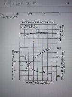
Meanwhile, degraded stability of the internal anode resistance ra (across the signal sweep) seems to be an obvious mechanism to look at.
Take the EL34 (Triode) curves I posted earlier. Check for yourself: a input swing of ~16V is enough to degrade ra by 10%; and 32V is enough to almost double ra.
And where the load-line (elipse, of course) opens up at low frequencies, the figures are notably worse.
Everyone knows that the calculated "anode load" formed by the output transformer should by multiples of ra for good performance, and here we see a shifting ra, that undermines the calculation.
EL34 and all the other pentodes and beam tubes were not designed to be run as triodes, so it's no surprise that this shortcoming was not an obstacle to their sales. In tetrode or pentode mode, none of this matters.
@bondini - as requested - Here's a few words from Marconi Osram's Engineering Team in the 1930s.
It proves that valve designers were perfectly aware that Unipotential (IDHT) cathodes were inferior to DHTs for output power valve design - which naturally means low and stable ra.

Notes:
1. the mention of "high gm" meant 5 - 8mA/V, in the 1930s
2. "Overall Efficiency of mutual conductance" means Conductance per Watt of Heating power
3. Source: HENDERSON, F.: "Introduction to Valves"; GEC Marconi-Osram, via Wireless World publishing desk, ca. 1938
It proves that valve designers were perfectly aware that Unipotential (IDHT) cathodes were inferior to DHTs for output power valve design - which naturally means low and stable ra.
Notes:
1. the mention of "high gm" meant 5 - 8mA/V, in the 1930s
2. "Overall Efficiency of mutual conductance" means Conductance per Watt of Heating power
3. Source: HENDERSON, F.: "Introduction to Valves"; GEC Marconi-Osram, via Wireless World publishing desk, ca. 1938

I had a friend years ago which was a hardcore fan of DHTs. One day he came over for listening to my new 300B build. As soon as I played the music he started praising the sound of THDs.
A little after that I switched to my triode strapped KT88 SET and he started talking about the lack of details, high THD etc..
You should see his face when I discovered I accidentally was using KT88 at the start and after that 300B. 🤣🤣
A little after that I switched to my triode strapped KT88 SET and he started talking about the lack of details, high THD etc..
You should see his face when I discovered I accidentally was using KT88 at the start and after that 300B. 🤣🤣
Last edited:
Rod - I don't understand "low and stable Ra".
Looking at 01A data sheet, Ra change is quite dramatic through Ik range. This is intrinsic for any triode, DH or IDH.
Re. uniformity of grid control over cathode length, Russian rod tubes are perfectly uniform.
Looking at 01A data sheet, Ra change is quite dramatic through Ik range. This is intrinsic for any triode, DH or IDH.
Re. uniformity of grid control over cathode length, Russian rod tubes are perfectly uniform.
Attachments
I have attached a chart showing changes in rp for three power triodes. The data was derived from the data sheets for:
The estimates plotted in the chart show that rp for the directly heated 300B remains more constant than rp for the indirectly heated KT88 and 6336A.

- the directly heated 300B using plate curves from the WE datasheet;
- the indirectly heated KT88 using the triode-connected plate curves from the Svetlana datasheet; and
- the indirectly heated 6336A using the plate curves from the Raytheon data sheet.
The estimates plotted in the chart show that rp for the directly heated 300B remains more constant than rp for the indirectly heated KT88 and 6336A.
You can make the rp flat as a pancake with some N Fdbk, but I haven't heard anyone say that, that gave the tube any "magic" sound.
The 300B holds rp steadier at the extremes of grid voltage (toward Vgk=0V and Vgk=-140V). On the basis of the data from the data sheets, if each triode was operated at Vgk=-70V and ia=75mA:
- there is little difference in the rate of variation of rp for each of the triodes over the range Vgk=-20V to Vgk=-120V (that is, swinging 50V either side of the bias point);
- which implies that, if variation in rp is the criterion in question, there would be little to pick between the three triodes for small signals and moderate signals; and
- in respect of steady rp, the 300B has an advantage when swinging voltages >50V : that is, when amplifying larger signals including large transient signals.
Triode vs tetrode or pentode.
6922 *30 (bjt) 200v
Compare with that and the curves are much closer. I get just under 30w with this.
6922 *30 (bjt) 200v
Compare with that and the curves are much closer. I get just under 30w with this.
In my experience NFB does make rp more flat and consequently it will decrease 2nd Harmonic dramatically, but somehow it will push energy into higher order harmonics and that supposedly would make the sound unpleasant to some people..You can make the rp flat as a pancake with some N Fdbk, but I haven't heard anyone say that, that gave the tube any "magic" sound.
I agree with you on this. IMO the distance between the plate curves across the load line is more important factor in linearity in oppose to a steady rp. That could be the main reason why 300B is so linear.It was convenient for the purposes of illustration for me to choose to estimate rp at a constant 75mA. I think it unlikely that any builder or designer would use a power triode this way.
That plus the driver circuit, I was able to get lower than 2.5 percent THD almost all 2nd order with 6336A at 8W using the correct driver.The actual measured performance (and its sonic performance) depends, as always,on the circuit in which the triode is employed.
This is probably a silly point of view, but a lot of the discussion of differences implies it is linked to distortion.
Our ears also are very sensitive to phase, since that is how we determine the source of a noise, and I think that is what is the secret sauce of a tube amplifier that we call 'staging'.
Amplifiers with directly heated tubes are also usually built with a low component count and good quality capacitors, preserving the phase or even accentuating it potentially.
Is it just incidental that DHT amplifiers sound better?
Hi, can I ask you to elaborate more this point? Thanks.preserving the phase or even accentuating it potentially
I think it would be a better expressed as:You can make the rp flat as a pancake with some N Fdbk, but I haven't heard anyone say that, that gave the tube any "magic" sound.
» the 'magic sound' arises (at least partly) because the best low-ra DHTs do not require closed-loop feedback to drive a loudspeaker with reasonably consistent drive-impedance.
» if ra is too variable, the drive impedance risks rising to non-negligible levels, and the effective Qts of the loudspeaker bounces up and down with the music level.
Our ears also are very sensitive to phase, since that is how we determine the source of a noise, and I think that is what is the secret sauce of a tube amplifier that we call 'staging'.
Being able to make a SE amplifier open loop, which DHTs do best (so, no feedback from the speaker) is a great help for the avoidance of phase shifts.
A closed-loop involving the tranformer/speaker almost certainly needs frequency compensation, and this rotates phase at higher audio frequencies; sometimes even in midrange.
Also, a typical 300B-SE amplifier only just has enough open-loop gain to drive the DHT to full output. Raising the gain another 15dB or so for some effective feedback usually means adding another stage, raising distortion and rotating the phase even more.
These problems can be solved to some degree, depending on the designer's ability - but an open-loop SE avoids the problem sufficiently for many loudspeakers.
The happy pairing of open-loop amps and sympathetic speakers is probably the best path to 'magic sound'
Care to share the driver information?I agree with you on this. IMO the distance between the plate curves across the load line is more important factor in linearity in oppose to a steady rp. That could be the main reason why 300B is so linear.
That plus the driver circuit, I was able to get lower than 2.5 percent THD almost all 2nd order with 6336A at 8W using the correct driver.
Of course my pleasure, here is the final schematics:Care to share the driver information?
And here is the test results:
This driver is able to produce 90V peak signal at power triode's grid. Based on the loadlines of both 12AU7s and 6336, it should produce a ton of distortion, but somehow it produces even less distortion than my 300b amp with 6SN7 cascode driver, and IMHO the sound is way better!
I wish if someone knowledgeable could give an explanation how most of the distortion got canceled here; because I've searched everywhere and there is only information about distortion cancelation in a cathode follower after the gain stage, both biased at the same point.
Put a largish triangle wave into the input and check the waveform at each stage thru the Amp for how it curves. Use safety attenuation and an isolation cap for the scope probe.
If the distortion is too low to see, then make an Op. Amp. integrator (feedback capacitor from Op Amp output to - input, with a high value resistor across it to keep DC gain under control. An input R to the - input sets the 1/gain for the integrator, with respect to the cap impedance at input triangle wave freq. ) Then Op. Amp. output goes to scope. Triangle wave will be converted to a square wave by the integrator. Use AC input mode on scope and crank the scope gain up to see how flat the + square wave tops are. Height of square wave tops is the gain at that tube stage versus triangle wave input voltage.
If the distortion is too low to see, then make an Op. Amp. integrator (feedback capacitor from Op Amp output to - input, with a high value resistor across it to keep DC gain under control. An input R to the - input sets the 1/gain for the integrator, with respect to the cap impedance at input triangle wave freq. ) Then Op. Amp. output goes to scope. Triangle wave will be converted to a square wave by the integrator. Use AC input mode on scope and crank the scope gain up to see how flat the + square wave tops are. Height of square wave tops is the gain at that tube stage versus triangle wave input voltage.
Last edited:
I still don't get it how more constant Rp at fixed plate current can affect the sound. An output triode doesn't work at constant current; both instantaneous voltage and current, as well as instantaneous Rp undergo pretty dramatic changes. Speaker damping only matters at its Fr and unlikely to account for sound differences between DHT and IDHT.
- Home
- Amplifiers
- Tubes / Valves
- What is the magic behind DHT tubes? Seriously...