IS there any logic to add a series resistor to a relay coil to lower coil current/watts/heat to enable a longer life span?
OR is that practice going to lower the pick-up tension of the contacts and lead them to overheat or not perform at their rated amperage?
Or does it just slow down contact response time?
I'm talking about 120 VAC 2500 ohm coils-ish and 15 amp loads on contacts.
120 volts drive and 120 volt slave relay controls in pinball machines and arcade console game machines.
Pure entertainment but in a retail/commercial establishment.
Cheers.
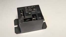
EDIT: I have always used octals in a socket but I have been asked to look at this type of relay for the purpose.
OR is that practice going to lower the pick-up tension of the contacts and lead them to overheat or not perform at their rated amperage?
Or does it just slow down contact response time?
I'm talking about 120 VAC 2500 ohm coils-ish and 15 amp loads on contacts.
120 volts drive and 120 volt slave relay controls in pinball machines and arcade console game machines.
Pure entertainment but in a retail/commercial establishment.
Cheers.
EDIT: I have always used octals in a socket but I have been asked to look at this type of relay for the purpose.
Attachments

Last edited:
I did it and it worked well, see R12+C7

C7 ensures that when you turn the relay on ("pull in" the relay as datasheets say), the full VDD supply voltage is applied across the terminals of the coil. Then gradually, R12 charges C7 and the voltage applied to the coil is reduced. A voltage divider is formed between R12 and the DC resistance of the relay coil. Rod Elliott published this circuit and its explanation (here), see Figure 6.2
C7 ensures that when you turn the relay on ("pull in" the relay as datasheets say), the full VDD supply voltage is applied across the terminals of the coil. Then gradually, R12 charges C7 and the voltage applied to the coil is reduced. A voltage divider is formed between R12 and the DC resistance of the relay coil. Rod Elliott published this circuit and its explanation (here), see Figure 6.2

Brilliant. Damn, I have seen this before.
How do I set this up on a 120 volt AC coil of 2500 ohms? Without 200 part count. Ha.
Load is 120 volts and the trigger is 120 volts.
How do I set this up on a 120 volt AC coil of 2500 ohms? Without 200 part count. Ha.
Load is 120 volts and the trigger is 120 volts.
Just put a power resistor in series to drop the voltage to whatever you want. Relays are often not exact for coil resistance, so the stated value is just a starting point in your calculations.
Normally a dropping resistor is used to adapt a relay to the supply voltage. A 24 volt relay on 35 volt rails for example. It is a very common practice. When replacing relays in a receiver you should always check the drop on the resistor (or coil voltage) is what it should be. Relays are not all the same even with the same coil voltage.
For pinball machines and solenoids on something like a tape machine, they often have a pull in supply, and a hold supply. Pull-in is often called "flash" or something like that. So the high supply is applied, and timed drops to the hold supply to conserve power. Normally a tapped winding on the power transformer, but you could use another transformer.
Funny. I was going to ask you, anatech, this question from the start, directly. Ha. Weird?Just put a powe...
I tested the relay in hand. I have them on my desk at home.
It snaps like a lobster claw with a 680 ohm 2 watt metal film in series with it.
The coils measure 2567 ohms and 2563 ohms respectively on the two relays I purchased.
They are controlled by a master switch panel. The panel runs all the machines in the night club. These relays are not going into machines.
I am using them as contactors remote out in the bar floor 100 feet away from the switch bank.
I'm worried the pull on the contacts will not be strong enough if I weaken the coil.
In past situations I would normally deploy a relay such as this with a small contactor after the relay.
It seems in excess in an isolated circuit that only draws 15 amp peak surge and operational current of 7-9 amps max.
It seems in excess in an isolated circuit that only draws 15 amp peak surge and operational current of 7-9 amps max.
Relays have tolerance on voltages. So a 120 VAC coil would be happy at 115 VAC, and you may well be seeing 125 VAC on your electrical panel. Have you measured your AC supply? It also may well vary during the day/night.
You want your initial pull-in to be smart, robust. There will be contact bounce, so you would use an spark quencher across the coils (CSA rated R-C network). Once the armature has pulled in, you don't need quite as much force from the coil, but given the reasonable current draw you may want to drop less voltage. Or just let run run at almost full voltage rated on the coil.
Understand that relays are maintenance items. They also make solid state relay modules, a "brick" with screw terminals on the top. Normally a control voltage turns them on and off. Given you are working across the line, a fuse followed by a spike varistor may save the electronics in equipment downstream. If you use a solid state switch, absolutely use spike suppression.
HP used it in their 14570A power controller of the early 1980s. It's a neat trick. Some relay drivers also have a similar function built in. The capacitor is critical, though. You do want to provide the full coil voltage until the relay has drawn. Then you can lower the voltage.Brilliant. Damn, I have seen this before.
Tom
I would use a bi-stable relay for this task. These change state when you apply a short impulse, then keep the state, using no energy, so no heat produced. They are exactly made for such task as yours.
You can place it near the consumer and switch them with a momentary button switch at low voltage, using a small transformer, like 15 Volt. That makes it possible to use thin, cheap wire from sender to receiver as well as small switches. No dangerous electricity in the swithing cirquit as well. For example a network cable could switch 7 relais, is very compact and dead cheap.
You want it even simpler? Get a remote switch set that does this wireless. Cheap and no installation requiered. You can install it inside the machine as well.
That's great. I suggest looking at the relay data sheet, though. Specifically, you need to find the hold voltage. You need to ensure that the voltage across the coil never drops below this value if you want the relay to remain engaged.It snaps like a lobster claw with a 680 ohm 2 watt metal film in series with it.
Tom
Also known as latching relays. Yep. That's another solid option.I would use a bi-stable relay for this task.
Tom
I'm focussing on THIS and dialing it in.You need to ensure that the voltage across the coil never drops below this value
I will find a safe compromise.
I'm just trying to save myself from replacing relays in a year or two from now.
The machines are all protected with modern electronics and even the old vintage games have reworked-guts. That has nothing to do with me.
My relay is cold and simple and does not call me back for ten years.
I misled you by writing: 120 volts drive and 120 volt slave relay controls 'IN' pinball machines and arcade console game machines.
oops
Not in.
EXTERIOR AC LINE CONTROLS
That is a HUGE difference. My Bad folks :-(
oops
Not in.
EXTERIOR AC LINE CONTROLS
That is a HUGE difference. My Bad folks :-(
Hi STOXX,
I would supply the coil with at least 90% of the rated voltage, probably closer. You want good contact closure, and the coil should be rated for continuous service. Your weak point should be contact failure, and that hasn't got anything to do with supplying voltage to the coil unless you don't provide enough operating current (applied voltage). Your replacement will be dependent on the load characteristics, not unless you buy cheap relays. Use arc quenching across the contacts to extend life.
I use plug in type, normally KUP style with sockets. They are indicating types to aid in troubleshooting so I know when it is energized. So if you do your part correctly, it will be reliable. The service life is dependent on load, and whatever happens such as overvoltage events. Mine are all 24 VDC run from a switching supply, coils switched with smaller relays (one relay controls a bank of KUP style relays). So my coils all run a the rated voltage, not lower. They have lasted well over 10 years to far. The stuff I work on is health and safety related, so I make it easy and really quick to troubleshoot and repair. I have a test mode built into the controller as well as an override. It is also as simple in design as possible, both for reliability, and so others can easily figure out what was done to repair it after I'm gone.
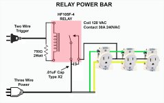
I didn't have any X2 caps so I used 15nF 1000VAC for now on the relay switch contacts. A 750 ohm 2 watt resistor worked well and kept the coil around 105~109 VAC. I tested on and off with a resistive/inductive heating element and a motor for 12 hours. Seems happy with a mixed load of 10 amps plus initial draw surges. I'm going to add a fuse to the relay coil and a 15 amp resettable breaker to the load side. I'm thinking LittleFuse PTCs.
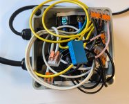
It is simple and it works. It is the power bar that steals logic from another circuit. Next time, I will look at solid state relays.
It is simple and it works. It is the power bar that steals logic from another circuit. Next time, I will look at solid state relays.
Attachments
Last edited:
Spaghetti Soup
Ha, now you can take that '300' WATT switched 'MAX' Outlet on the back of your preamp or receiver and power more.
Ha, now you can take that '300' WATT switched 'MAX' Outlet on the back of your preamp or receiver and power more.
Attachments
Last edited:
I did it and it worked well, see R12+C7
C7 ensures that when you turn the relay on ("pull in" the relay as datasheets say), the full VDD supply voltage is applied across the terminals of the coil. Then gradually, R12 charges C7 and the voltage applied to the coil is reduced. A voltage divider is formed between R12 and the DC resistance of the relay coil. Rod Elliott published this circuit and its explanation (here), see Figure 6.2
It's definitely a clever circuit, but it doesn't work quite the way you think - R12 is in parallel with C7.
When the relay is off, R12 ensures that C7 discharges. When the relay coil is first energized, C7 for practical purposes looks like a short as it is fully discharged, and as a result applies nearly the full voltage across the relay coil, energizing and pulling it in. C7 then charges through the resistance of the relay coil until reaches the voltage that would be across R12 if it were in series with the energized relay coil by itself (without the cap in the circuit). Once the cap has charged to this level, it is effectively out of the circuit and it then acts like a simple series circuit consisting only of R12 and the relay coil, resulting in a lower current through the coil. When the relay is turned off, R12 then discharges C7 to be ready for the next turn on.
-Pat
I think you mean "charges through the Thevenin equivalent resistance of (R12 and the DC resistance of the relay coil)"
The final asymptotic voltage across the relay coil after ten seconds is the Thevenin equivalent voltage, and is equal to (Vdd - Vss) * (Rcoil / (Rcoil + R12))
The Thevenin equivalent resistance is equal to (R12 parallel Rcoil)
The final asymptotic voltage across the relay coil after ten seconds is the Thevenin equivalent voltage, and is equal to (Vdd - Vss) * (Rcoil / (Rcoil + R12))
The Thevenin equivalent resistance is equal to (R12 parallel Rcoil)
Last edited:
- Home
- Design & Build
- Electronic Design
- Adding a resistor in series with relay coil?