People always talk about JFET in the input stage, but nobody talk about using MOSFET in the input stage.
The only reason that I could find is MOSFETs have high noise figure. How high is too high? Does it matter in the power amplification context? It is not a preamp.
As JFETs are pretty delicate, the voltage rating is pretty low. You have to babysit them. In contrast, you can find MOSFETs with voltage rating from 60v to 240v in TO-92 package easily.
In my simulation, BS170 is more linear, lower distortion, higher transconductance than 2SK170. Why don't we use MOSFET?
No talk but there is action:
https://www.diyaudio.com/community/threads/babelfish-f8.419127/post-7906167
https://www.diyaudio.com/community/threads/babelfish-f8.419127/post-7906167
It’s merely used as a input buffer in that Babelfish circuit, though. Within the capability limits of IC op-amps, there are, of course, CMOS input stage devices. Such as the OPA1656, and the OPA2156
If its low source impedance (voltage noise dominant) BJT's can outperform any FET for noise and linearity (*), and most amplifier imputs are driven with low impedance for solid-state gear at least. BJTs are more susceptible to RFI though.
For higher impedance FETs are typically lowest noise as current noise dominates, and both types of FET have negligible current noise in most situations.
So its only using FETs at low or middle impedances where JFET v. MOSFET will matter (i.e. where voltage noise performance matters), and JFETs are currently better for noise there.
A useful parameter of a device is voltage noise density / current noise density - this gives the ideal source resistance for getting the best out that device. For BJT's its more complex as that parameter depends on collector current (which affects both types of noise density).
If JFETs are delicate, MOSFETs are more so due to gate oxide layer.
1/f noise knee-frequencies are another concern to be aware of, and annoyingly are usually different for current and voltage noise.
(*) by virtue of high transconductance.
I think some early Pass amps and the earlier revision of Acoustat's TransNova amps use MOSFETs as diff. input devices, too.
In for example LTP input there is this used:
1. Bipolar
2. JFET
3. MOSFET
No doubt the bipolar is the most used. No competition about that.
JFET has qualities bipolar has not. Like small input current.
But they have low max voltage. This can however be overcome with cascoding.
MOSFET are interesting alternative.
Deserves to be some investigation of this.
There are not too many TO-92 mosfets worth using.
MOSFET threshold voltage "Vth" varies tremendously, even moreso than JFET pinchoff voltage "Vp". So it's time consuming and tedious to test a big pile of MOSFETs in the hopes of finding an input pair whose Vth's match within 2 millivolts. (Unit-to-unit variability isn't included in garden variety simulation programs)
Manufacturers aren't building many discrete MOSFETs targeted towards small signal linear circuits; instead, they optimize their MOSFET products for fast and efficient switching circuits. Low on-resistance and low total-gate-charge are the parameters of interest. Thus the MOSFETs you can buy, are built to handle 10X - 100X more current than you'll actually apply in an audio amplifier's input stage. And that means: higher capacitance than you'd like. Gate-to-drain capacitance of the MOSFETs you can buy today, is significantly higher than gate-to-drain capacitance of JFETs. You can deal with this using bootstrapped cascodes but that's messy.
Manufacturers aren't building many discrete MOSFETs targeted towards small signal linear circuits; instead, they optimize their MOSFET products for fast and efficient switching circuits. Low on-resistance and low total-gate-charge are the parameters of interest. Thus the MOSFETs you can buy, are built to handle 10X - 100X more current than you'll actually apply in an audio amplifier's input stage. And that means: higher capacitance than you'd like. Gate-to-drain capacitance of the MOSFETs you can buy today, is significantly higher than gate-to-drain capacitance of JFETs. You can deal with this using bootstrapped cascodes but that's messy.
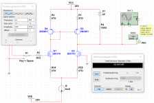
Here is the simulation. Same bias, at 2mA on each transistor. I tweak the degenerative resistors to let them have the same output voltage swing. 400mVpp. Thus, overall, they all have same transconductance(gm). They all are driven by a voltage source that has low output impedance.
It looks like the distortion is inverse relation to the degenerative resistor. The bigger the resistor, the more linear it is. That makes sense. As BJT has very high gm, you could use larger degenerative resistor to get the same overall gm of the input stage.

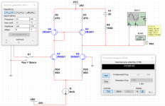
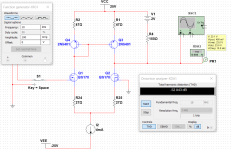
It looks like the distortion is inverse relation to the degenerative resistor. The bigger the resistor, the more linear it is. That makes sense. As BJT has very high gm, you could use larger degenerative resistor to get the same overall gm of the input stage.


Last edited:
Another run with 2K Ohm source impedance. The typical impedance you get when you put a volume pot at the input. Note that BJT looses output swing almost 10%. That might be more important than the THD degradation. That means, BJT has less overall gm. Less gm at input stage, means less NFB around output stage, which results even higher distortion.
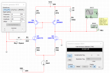
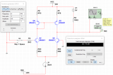


I did some MOSFET noise measurements years ago, but actually not MOSFETs with a high voltage handling, rather cheap low-voltage MOSFETs that are integrated on a chip with some colleagues. I considered the noise to be good enough for a line-level input, but other people may have other requirements.
It depends a bit on the constraints. When there are no constraints on silicon area/number of paralleled devices and supply current, FETs can always outperform bipolar transistors because at audio frequencies, they have a lower product of their equivalent input noise voltage and equivalent input noise current. (Just connect so many JFETs in (AC) parallel (while increasing the total current to keep the drain current per JFET constant) that the voltage noise gets somewhat smaller than that of the bipolar stage, and you will still have less noise current than that of the bipolar stage.) When there are constraints on current or area, then I agree completely. As an example of a dual JFET that must have a huge area (and is quite expensive): https://www.interfet.com/jfet-datasheets/jfet-if3602-interfet.pdf
Hi all,
Dual JFETs are often difficult to get and I didn't fancy selecting matched devices myself. Therefore, I've been looking at some hex PMOSFET/NMOSFET combinations that are also known as hex unbuffered inverters. Noise and offset are totally uncharacterised, of course, but they actually aren't too bad. I measured four SN74HCU04N's and ten SN74AHCU04N's and got by far the best results from the SN74AHCU04N's.
See the attached schematic. The numbers in the schematic are in Dutch, so the decimal separator is a comma rather than a point. The numbers below refer to the quad...
If its low source impedance (voltage noise dominant) BJT's can outperform any FET for noise and linearity (*), and most amplifier imputs are driven with low impedance for solid-state gear at least.
It depends a bit on the constraints. When there are no constraints on silicon area/number of paralleled devices and supply current, FETs can always outperform bipolar transistors because at audio frequencies, they have a lower product of their equivalent input noise voltage and equivalent input noise current. (Just connect so many JFETs in (AC) parallel (while increasing the total current to keep the drain current per JFET constant) that the voltage noise gets somewhat smaller than that of the bipolar stage, and you will still have less noise current than that of the bipolar stage.) When there are constraints on current or area, then I agree completely. As an example of a dual JFET that must have a huge area (and is quite expensive): https://www.interfet.com/jfet-datasheets/jfet-if3602-interfet.pdf
Last edited:
I also find the reverse transfer capacitance of the jfet could be quite big. This link is a good example. It is bigger than most of mosfet in to-92 package. Combining it with feedback resistor network, it creates an additional pole around 1MHz-10MHz. It may cause stability issue.When there are constraints on current or area, then I agree completely. As an example of a dual JFET that must have a huge area (and is quite expensive): https://www.interfet.com/jfet-datasheets/jfet-if3602-interfet.pdf
I don't think anyone in their right mind would use an IF3602 for line level audio, much smaller and cheaper JFETs with much less capacitance would suffice for that. At Mouser, an IF3602 costs $74.63.
I just take that for example. The famous p channel jfet 2sj74 has Crss specified at 32pf. It starts to cut into the gain/phase margin of the entire amp.
The famous p channel 2sj74 has Crss specified at 32pf. It starts to cut into the gain/phase margin of the entire amp.
gate-to-drain capacitance of JFETs. You can deal with this using bootstrapped cascodes but that's messy.
Some small signal MOSFETs look quite promising:
BSS84/BSS84P (P)
BSS123, 2N7002 (N)
In fact, several of the BSSxx series look interesting in the datasheets and simulation.
Forward transconductance for the BSS84:

50 milli-Siemens minimum gain, and 600mS typical.
BSS84/BSS84P (P)
BSS123, 2N7002 (N)
In fact, several of the BSSxx series look interesting in the datasheets and simulation.
Forward transconductance for the BSS84:
50 milli-Siemens minimum gain, and 600mS typical.
Forward transconductance
Forward transconductance, often denoted as ( g_{fs} ), is a measure of the sensitivity of the drain current (( I_D )) to changes in the gate-source voltage (( V_{GS} )) in a MOSFET, expressed in units of Siemens.
The J110 and J174 look like they can maybe handle up to 100mA, but I couldn't find their gm "figure of merit". Does anyone know the relationship between noise and gain? It seems that since the device gain contributes directly to loop gain, the total noise can be divided down by the feedback level.Jfet gm
The transconductance (gm) of a JFET is defined as the change in drain current (ID) with respect to a change in the gate-to-source voltage (VGS)
The white part of the equivalent input noise voltage is some correction factor times the thermal noise of 1/gm. If I remember well, the correction factor c is theoretically 2/3, but can be anything up to about 2 in reality. That is, the RMS value of the white part of the noise over a bandwidth ∆f is √(4kTc∆f/gm).
This says absolutely nothing about the 1/f part, which tends to be far worse for MOSFETs than for JFETs. It improves by about 10 dB for every factor of ten increase of the gate area. For a given area, PMOSFETs usually have less 1/f noise than NMOSFETs (MOSFETs in some deep submicron IC processes excepted).
This says absolutely nothing about the 1/f part, which tends to be far worse for MOSFETs than for JFETs. It improves by about 10 dB for every factor of ten increase of the gate area. For a given area, PMOSFETs usually have less 1/f noise than NMOSFETs (MOSFETs in some deep submicron IC processes excepted).
Last edited:
A MOSFET has a truly insulated gate (unless ESD protected) so there might be some niche applications there, but most of the time it may be risky for that reason alone.
What about a cascode input?
So you have something like a headphone jack or line stage, already designed for heavy lifting like 1k ohm. If it's only loaded down with something like 1M ohm and input capacitance, that non-linear load could propagate into the pre-amp. But if the pre-amp is buffered with a degenerated source/emitter, and the drain/collector output then drives a resistor-loaded gate, the cascode almost completely shields the pre-amp from whatever the amplifier is doing downstream.
If it's only loaded down with something like 1M ohm and input capacitance, that non-linear load could propagate into the pre-amp.
It's unclear to me what you mean. A low-impedance output should have no trouble driving 1 Mohm in parallel with a small non-linear capacitor as far as I can tell.
MOSFET threshold voltage "Vth" varies tremendously, even moreso than JFET pinchoff voltage "Vp". So it's time consuming and tedious to test a big pile of MOSFETs in the hopes of finding an input pair whose Vth's match within 2 millivolts. (Unit-to-unit variability isn't included in garden variety simulation programs)
Manufacturers aren't building many discrete MOSFETs targeted towards small signal linear circuits; instead, they optimize their MOSFET products for fast and efficient switching circuits. Low on-resistance and low total-gate-charge are the parameters of interest. Thus the MOSFETs you can buy, are built to handle 10X - 100X more current than you'll actually apply in an audio amplifier's input stage. And that means: higher capacitance than you'd like. Gate-to-drain capacitance of the MOSFETs you can buy today, is significantly higher than gate-to-drain capacitance of JFETs. You can deal with this using bootstrapped cascodes but that's messy.
Anybody checked out MOSFET pairs? I wonder how closely they are Vgs matched?
Most MOSFET datasheets are lacking when it comes to linear parameters such as noise and behavior at lower currents, so unless you're willing to do some tests yourself, then it's difficult to design linear circuits with them.
Yes, I hadn't really refined that idea. A light load helps with small coupling capacitors, but a separate issue could be a poor impedance match if a high capacitance cable is terminated with that 1M ohm.It's unclear to me what you mean. A low-impedance output should have no trouble driving 1 Mohm in parallel with a small non-linear capacitor as far as I can tell.
- Home
- Amplifiers
- Solid State
- MOSFET vs JFET in The Input Stage