At message #630 I had one possible schema, but it have troubles when temperature changes and it always changes little or more. As you see Q4:s Vbe voltage biases also second P-jfet and fet's bias drift with temperature. With constant temperature this one works quite well.
So, here is the next try, to name it , it can be FeG2. This one is more a standard textbook solution.

And the protype looks like this. Diode D1 is qlued over Q4 and this is important for DC stability to keep these parts around same temperature.

This really works, measured distortion is 0.35% at 5mV input. Gain is around 43dB. And it sounds good. Distortion is mainly second harmonic look the smaller trace here which is taken from distortion analyzers output. Max. input voltage is around 50mV and more voltage in makes output stage clip. Good enough from this simple design.


Many members seems to have new or almost new measuring equipment but these old work as well.
So, here is the next try, to name it , it can be FeG2. This one is more a standard textbook solution.
And the protype looks like this. Diode D1 is qlued over Q4 and this is important for DC stability to keep these parts around same temperature.
This really works, measured distortion is 0.35% at 5mV input. Gain is around 43dB. And it sounds good. Distortion is mainly second harmonic look the smaller trace here which is taken from distortion analyzers output. Max. input voltage is around 50mV and more voltage in makes output stage clip. Good enough from this simple design.
Many members seems to have new or almost new measuring equipment but these old work as well.

Interesting, but with the all emitter degeneration, the drift are affecting clipping, distortion, or both?
About equipment, some members have PC-based ones (for a example 🙂
About equipment, some members have PC-based ones (for a example 🙂
Drift changes only DC currents trough Q3 and Q4. Distortion must be same with emitter degeneration. Can affect clipping if temperature changes a lot, say 10 degrees of Celsius. In any case both circuits works quite well.
One circuit that I need to locate where I saved the schematic...
A amplifier I built 3 years ago, using output very much like the Susan Parker Zeus (output buffer), but using Ge transistors for the output: in this case, 1T905 and 1T910 forming a Ge darlington, with generous bias. In curve traces, it have very good low saturation voltage, excellent for low voltage projects. Like this: for my amp, the louspeakers are directly connected to emitters of the outputs (then, the output trafo is a CT choke). Then the PSU needs to have far lower voltage, due to brutal low impedance seen by the transistors (especially when enters the class B region). Only 9V for the +B; the CT choke makes it like almost 4 times it's value (like for every PP trafo amp). Driven by a 2P29P pentode input, CCS loaded, with a MOSFET follower using a 2SK216 for driving the interestage trafo. With that, I obtained the following measurement results:


Even with 8W, the distortion was lower than 0.07%, with 8R load. Without any global or interestage feedback (only the foloower action). With great harmonic content.
0.017% at 1W with excellent harmonic content.
Without load:

Interesting, the output stage are holding of this own; not much changes with load at this point!
Of course, iron elevated HD at lower frequencies (due to finite impedance driving, more probably due to interestage). Only a little increase for the HF part due to trafos. NOTE: in fact, in the sweep measurements, the 20kHz HD is lower compared with lower frequencies.
The sound? Excellent, I cannot discern it from my main tube amplifier with PL509 at that time. Probably, with more time and effort. This is rare to occur in my lounge... ;-) But, I needed it's heatsink for another project and disassembled it.
Was a shame, probably I need to re-assemble it.
A amplifier I built 3 years ago, using output very much like the Susan Parker Zeus (output buffer), but using Ge transistors for the output: in this case, 1T905 and 1T910 forming a Ge darlington, with generous bias. In curve traces, it have very good low saturation voltage, excellent for low voltage projects. Like this: for my amp, the louspeakers are directly connected to emitters of the outputs (then, the output trafo is a CT choke). Then the PSU needs to have far lower voltage, due to brutal low impedance seen by the transistors (especially when enters the class B region). Only 9V for the +B; the CT choke makes it like almost 4 times it's value (like for every PP trafo amp). Driven by a 2P29P pentode input, CCS loaded, with a MOSFET follower using a 2SK216 for driving the interestage trafo. With that, I obtained the following measurement results:
Even with 8W, the distortion was lower than 0.07%, with 8R load. Without any global or interestage feedback (only the foloower action). With great harmonic content.
0.017% at 1W with excellent harmonic content.
Without load:
Interesting, the output stage are holding of this own; not much changes with load at this point!
Of course, iron elevated HD at lower frequencies (due to finite impedance driving, more probably due to interestage). Only a little increase for the HF part due to trafos. NOTE: in fact, in the sweep measurements, the 20kHz HD is lower compared with lower frequencies.
The sound? Excellent, I cannot discern it from my main tube amplifier with PL509 at that time. Probably, with more time and effort. This is rare to occur in my lounge... ;-) But, I needed it's heatsink for another project and disassembled it.
Was a shame, probably I need to re-assemble it.
Last edited:
I had a bit of a basic question, but thought I'd ask those on the thread.
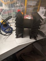
I have a quad of unmarked W.E. Ge power transistors, supposedly good for 50W dissipation at 25°C that I'm hoping to try in a simple Class A SE amp. (With choked collector or emitter)
Before I can try and make basic curves and see what I'm dealing with, I'm wondering about how to mount it to a heat sink.
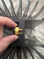
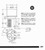
Strangely, the collector thread has a ~1/16 inch raised "seat": it's not flush with the emitter/base leads. I can't understand why, as the smaller seat diameter is only ~45% of the larger dia.
I'm mostly wondering if the small 0.455" seat dia would be enough surface area to run the transistor at up to, say, 19W dissipation? (I have a 19V Mean Well, I figure 1A would be the max Ic I would aim for) I'm really trying to keep the device temperature as low as possible. (I saw that TO-220 parts might have a slightly smaller collector area, which gives me a little hope)
I have a large heatsink, but would need to drill clearance for the transistor to about half the depth of the mounting shelf (from bottom). I'm thinking this might result in less thermal resistance than using a separate (much thinner) spreading plate.
(I might even try mount a 2nd transistor and try PP)
Appreciate any pointers anyone can give.
I have a quad of unmarked W.E. Ge power transistors, supposedly good for 50W dissipation at 25°C that I'm hoping to try in a simple Class A SE amp. (With choked collector or emitter)
Before I can try and make basic curves and see what I'm dealing with, I'm wondering about how to mount it to a heat sink.
Strangely, the collector thread has a ~1/16 inch raised "seat": it's not flush with the emitter/base leads. I can't understand why, as the smaller seat diameter is only ~45% of the larger dia.
I'm mostly wondering if the small 0.455" seat dia would be enough surface area to run the transistor at up to, say, 19W dissipation? (I have a 19V Mean Well, I figure 1A would be the max Ic I would aim for) I'm really trying to keep the device temperature as low as possible. (I saw that TO-220 parts might have a slightly smaller collector area, which gives me a little hope)
I have a large heatsink, but would need to drill clearance for the transistor to about half the depth of the mounting shelf (from bottom). I'm thinking this might result in less thermal resistance than using a separate (much thinner) spreading plate.
(I might even try mount a 2nd transistor and try PP)
Appreciate any pointers anyone can give.
Attachments
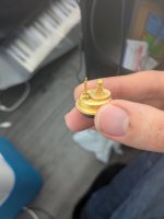
Those look a lot like old car radio Ge power transistors. If so, they were not rated for very high DC voltage, like on the order of 20 VDC C-E breakdown. Those were class A amplifiers in the most rudimentary sense.
Pretty similar, yes - though that example seems to have the base/emitter leads at the same level as the collector - unlike mine, unfortunately.This case looks similar, doesn't it ?
The person I picked them up from mentioned seeing ratings of 50 or 60VDC max, but that's the extent of the info I have. Hopefully they'd make for an interesting experiment.they were not rated for very high DC voltage,
Well, do initial experiments below 20 VDC. Then maybe measure leakage current and increase C-E voltage until it starts to come up. It would be a shame to kill them unnecessarily before you can have fun with them.
I threw a bunch of that case style out maybe 35 years ago. They had no purpose anymore, being for old car radios. I kept some TO-3 cases and recently used a pair to fix a 1960's stereo unit. I honestly didn't think I would ever use one!
I threw a bunch of that case style out maybe 35 years ago. They had no purpose anymore, being for old car radios. I kept some TO-3 cases and recently used a pair to fix a 1960's stereo unit. I honestly didn't think I would ever use one!
Yep, might even try some battery bias just to do quick tests. Thanks for reminder about checking leakage.
Ah that's dedication to keeping a potentially useful part on hand. Must have been satisfying.I kept some TO-3 cases and recently used a pair to fix a 1960's stereo unit. I honestly didn't think I would ever use one!
Yes!This really works,
Try to make PS from Ge elements too. Like EMT does in some designs? One example Noise X module... And others too.
And maybe copper plate board under the elements? As ground plane. Everything else can be the same. I like Point to point.
Great design HLH BTW
🙂 Thanks
With a low noise fan you can achieve good dissipation. Without any fan, will be difficult to maintain low junction temperature and operation suffers.I had a bit of a basic question, but thought I'd ask those on the thread.
I have a quad of unmarked W.E. Ge power transistors, supposedly good for 50W dissipation at 25°C that I'm hoping to try in a simple Class A SE amp. (With choked collector or emitter)
Before I can try and make basic curves and see what I'm dealing with, I'm wondering about how to mount it to a heat sink.
Strangely, the collector thread has a ~1/16 inch raised "seat": it's not flush with the emitter/base leads. I can't understand why, as the smaller seat diameter is only ~45% of the larger dia.
I'm mostly wondering if the small 0.455" seat dia would be enough surface area to run the transistor at up to, say, 19W dissipation? (I have a 19V Mean Well, I figure 1A would be the max Ic I would aim for) I'm really trying to keep the device temperature as low as possible. (I saw that TO-220 parts might have a slightly smaller collector area, which gives me a little hope)
I have a large heatsink, but would need to drill clearance for the transistor to about half the depth of the mounting shelf (from bottom). I'm thinking this might result in less thermal resistance than using a separate (much thinner) spreading plate.
(I might even try mount a 2nd transistor and try PP)
Appreciate any pointers anyone can give.
All I'll add is that all semiconductors are heat sensitive. Germanium is more so. So whatever you do, keep them as cool as you possible can. I wouldn't push them, they will fail sooner even it it works. If you look at older equipment using Germanium power transistors you will see the heat sinks are larger than units using silicon transistors. There is a hint in there.
You will see more class A designs with germanium parts. That is simply because engineering thinking was still mostly tube based. We were still learning how to use semiconductors. Designs shifted as we learned, silicon simply came along during that process, plus they were cheaper and more reliable. Aside from higher beta, Germanium devices offered no advantages over silicon. So treat them gently, they are not as rugged as the parts we are used to using today.
You will see more class A designs with germanium parts. That is simply because engineering thinking was still mostly tube based. We were still learning how to use semiconductors. Designs shifted as we learned, silicon simply came along during that process, plus they were cheaper and more reliable. Aside from higher beta, Germanium devices offered no advantages over silicon. So treat them gently, they are not as rugged as the parts we are used to using today.
For germanium, direct contact with a thick radiator is extremely important. Without gaskets.
Of course, with thermal paste.
Then you can do without a cooler. With its noise
Germanium has an advantage over silicon.
Find a more linear pentode characteristic

Of course, with thermal paste.
Then you can do without a cooler. With its noise
Germanium has an advantage over silicon.
Find a more linear pentode characteristic
Hi Svjatoslav,
By the term "cooler", you mean a fan I guess. Absolutely correct. A fan is just another point of failure, collects dust and is noisy. People tend not to maintain fan filters in my experience.
I would say that the transfer characteristic is more similar to silicon than it is different. The transfer curve for Germanium shows more of a heat effect. Too bad the problems with Germanium outweigh the benefits, leakage that increases with age is a real problem.
Congratulations!
Durability depends on the degree of load. If it is not higher than 40%, then it will work even for our great-grandchildren.
The mode stabilization system can also be made on silicon. Or a simple servo, as in germanium circlotrons
Very good germanium - transistors using conversion technology.
I don't know if there are such in Western countries.
They are very resistant to overload, especially in peak current.
But they have additional characteristics to powerful diffusion technology.
This is a well-tested combination.
I only know of a pair available in my area:
P605A/GT806
The first is conversion, the second is diffusion.
Last edited:
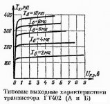
Svjatoslav, GT404 is perhaps the whole exception. Even his pair GT402 is no longer enviable.Find a more linear pentode characteristic
Attachments
That's right.
Especially high linearity n-p-n germanium. Especially alloyed.
In p-n-p this indicator is lower.
By the way, in bipolar silicon it is the opposite
Especially high linearity n-p-n germanium. Especially alloyed.
In p-n-p this indicator is lower.
By the way, in bipolar silicon it is the opposite


- Home
- Amplifiers
- Pass Labs
- Germanium investigations