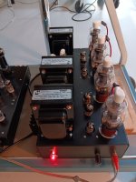
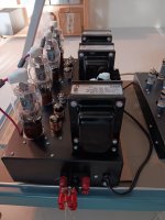
As I just like the look of the old 807 tubes I decided to build a amplifier based on the 1930s 807 type.
As I recently finished the build I thought I would post the results in case it was of interest.
Is this finest sounding amplifier ever built? No not even close but for the first beam power tube technology of the 1930s it does perform surprisingly well.
Total THD at 1 watt is below 0.05% and at 1Khz and below 0.2% at 40 watts output. At 20Khz THD is below 0.4% at full power and under 0.05% at 30HZ again at full power.
At 1 watt the THD is mostly second harmonic, however it transitions to mostly third harmonic above about 5 watts.
The 807s plates run at 510V into a P-P impedance of 6600 ohms , with fixed bias and regulated screens set to 350V.
The screens are provided with a portion of the plate AC signal voltage in a variation on the classic UL mode of operation.
Running the 807 in UL mode really helped tame some of the 807s bad habits and greatly helped with stability in general.
There are also large ferrite sleeves on each plate lead , 1K screen resistors and 100 ohm grid stoppers.
The 350V on the screens may seem high as the tubes are rated at only 300V but that is in pentode mode.
In triode mode the screen can be run to 400 volts according to some data sheets.
The way I am running the 807 screen the 350V on the screen is modulated by the plate AC voltage and so drops to about 275 volts at minimum plate voltage where
maximum screen current occurs.
This greatly limits the screen power dissipation at full power while still providing good plate current and drops the output tube distortion to about 1/2.
I chose to drive the 807s with a cathode follower for two reasons. First it allow for a low DC impedance on the 807 grids
This stabilizes the bias current in the presence of any grid leakage when the tubes are run hard.
Second it allows a smooth transition into class AB2 at high power instead of clipping and blocking distortion that most class AB1 designs enter at zero grid volts.
This provides extra output power and a fast recovery for any clipping. Class AB2 is entered at about 25 watts output and extends power to 40 watts.
The cathode follower is driven by a LTP pulled to a -120V rail by a high value resistor.
The cathode resistor does not provide the perfect balance of a current source but the small error is easily trimmed out with a POT during amplifier setup.
As a balance adjustment is helpful for correcting output tube gain errors the adjustment is needed anyway.
I stuck with a resistor as it is simple and bullet proof and importantly low in distortion at 20Khz where many current sources have increased THD and loss of impedance do to speed issues within the current source.
The input stage is a simple pentode amplifier using a 6AK5. Nothing fancy here but the 6AK5 can provide a lot of low distortion gain.
The 6AK5 is direct coupled to the LTP to limit phase shift in the amplifier and only one coupling capacitor is used between the LTP and the cathode follower.
The screen is bypassed by a 100nF capacitor to the cathode to increase gain. The capacitor value is chosen to insure low frequency stability by providing a shelving in the low frequency gain. Further LF phase compensation is proved by a large value cathode capacitor, resistor network.
Feedback is injected into the 6AK5 cathode from the 8 ohm speaker tap.
The result is a stable amplifier that is perfectly happy and stable at high and low frequencies with no load on the transformer secondary.
All rails are regulated except the 510V B+ on the 807 plates.
This provides a lot of added margin in the output tubes by stabilizing all voltages and currents and makes the amplifier mostly immune to line voltage variation.
Hum is banished as well.
The cost of regulated rails is complexity, there is no denying it.
Regulated rails are great for performance and stability but exact a price in complexity.
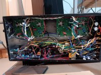
Here are some pictures of the newly finished build.
It is pretty busy inside and there is some wiring cleanup still to go.
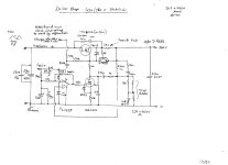
I also posted the circuit diagram.
Now there will be a burn in for a few weeks providing background music in my lab.
As I recently finished the build I thought I would post the results in case it was of interest.
Is this finest sounding amplifier ever built? No not even close but for the first beam power tube technology of the 1930s it does perform surprisingly well.
Total THD at 1 watt is below 0.05% and at 1Khz and below 0.2% at 40 watts output. At 20Khz THD is below 0.4% at full power and under 0.05% at 30HZ again at full power.
At 1 watt the THD is mostly second harmonic, however it transitions to mostly third harmonic above about 5 watts.
The 807s plates run at 510V into a P-P impedance of 6600 ohms , with fixed bias and regulated screens set to 350V.
The screens are provided with a portion of the plate AC signal voltage in a variation on the classic UL mode of operation.
Running the 807 in UL mode really helped tame some of the 807s bad habits and greatly helped with stability in general.
There are also large ferrite sleeves on each plate lead , 1K screen resistors and 100 ohm grid stoppers.
The 350V on the screens may seem high as the tubes are rated at only 300V but that is in pentode mode.
In triode mode the screen can be run to 400 volts according to some data sheets.
The way I am running the 807 screen the 350V on the screen is modulated by the plate AC voltage and so drops to about 275 volts at minimum plate voltage where
maximum screen current occurs.
This greatly limits the screen power dissipation at full power while still providing good plate current and drops the output tube distortion to about 1/2.
I chose to drive the 807s with a cathode follower for two reasons. First it allow for a low DC impedance on the 807 grids
This stabilizes the bias current in the presence of any grid leakage when the tubes are run hard.
Second it allows a smooth transition into class AB2 at high power instead of clipping and blocking distortion that most class AB1 designs enter at zero grid volts.
This provides extra output power and a fast recovery for any clipping. Class AB2 is entered at about 25 watts output and extends power to 40 watts.
The cathode follower is driven by a LTP pulled to a -120V rail by a high value resistor.
The cathode resistor does not provide the perfect balance of a current source but the small error is easily trimmed out with a POT during amplifier setup.
As a balance adjustment is helpful for correcting output tube gain errors the adjustment is needed anyway.
I stuck with a resistor as it is simple and bullet proof and importantly low in distortion at 20Khz where many current sources have increased THD and loss of impedance do to speed issues within the current source.
The input stage is a simple pentode amplifier using a 6AK5. Nothing fancy here but the 6AK5 can provide a lot of low distortion gain.
The 6AK5 is direct coupled to the LTP to limit phase shift in the amplifier and only one coupling capacitor is used between the LTP and the cathode follower.
The screen is bypassed by a 100nF capacitor to the cathode to increase gain. The capacitor value is chosen to insure low frequency stability by providing a shelving in the low frequency gain. Further LF phase compensation is proved by a large value cathode capacitor, resistor network.
Feedback is injected into the 6AK5 cathode from the 8 ohm speaker tap.
The result is a stable amplifier that is perfectly happy and stable at high and low frequencies with no load on the transformer secondary.
All rails are regulated except the 510V B+ on the 807 plates.
This provides a lot of added margin in the output tubes by stabilizing all voltages and currents and makes the amplifier mostly immune to line voltage variation.
Hum is banished as well.
The cost of regulated rails is complexity, there is no denying it.
Regulated rails are great for performance and stability but exact a price in complexity.
Here are some pictures of the newly finished build.
It is pretty busy inside and there is some wiring cleanup still to go.
I also posted the circuit diagram.
Now there will be a burn in for a few weeks providing background music in my lab.
Attachments


Seems really interesting. Thank you for sharing your design and build. The amplifier looks great!
I’m trying to understand your scheme to modulate screen voltage, and find it ingenious. A way to provide UL feedback to the screen while maintaining a reasonable screen voltage on output tubes with “fragile screens”, such as all those TV sweeptubes out there. Do you have any references for this approach? I have not encountered this approach before and would like to read up on it. The schematics for the regulators appears to be missing though.
What software produced these diagrams? I found it hard to read initially, but with a bit of determination and following the tags I think I got the “picture”. One item I am still missing is how you adjust bias to run the 807’s at 30 ma each.
The way I am running the 807 screen the 350V on the screen is modulated by the plate AC voltage and so drops to about 275 volts at minimum plate voltage where
I’m trying to understand your scheme to modulate screen voltage, and find it ingenious. A way to provide UL feedback to the screen while maintaining a reasonable screen voltage on output tubes with “fragile screens”, such as all those TV sweeptubes out there. Do you have any references for this approach? I have not encountered this approach before and would like to read up on it. The schematics for the regulators appears to be missing though.
What software produced these diagrams? I found it hard to read initially, but with a bit of determination and following the tags I think I got the “picture”. One item I am still missing is how you adjust bias to run the 807’s at 30 ma each.
I am curious about what you consider your finest buildsIs this finest sounding amplifier ever built? No not even close
This 807 amp reminds me of the 2nd amp I had in 1966, the Linear Concord fitted with 807´s instead of EL34´s with an increased B+but with basic cap filtering and no choke. Many amps of that era followed the LTP convention. Is a museum piece but at that time it was no wonder that it was a cap destroyer... The negative bias derived from a lifted centre tap on the mains transformer was not particulary elegant method when things started to go wrong, which they often did on moments not required.
Bench Baron
Bench Baron
Thanks for sharing. This is my version of a 807 PP amplifier:
https://www.diyaudio.com/community/threads/push-pull-807-amplifier-without-global-nfb.384100/
https://www.diyaudio.com/community/threads/push-pull-807-amplifier-without-global-nfb.384100/
No I do not have a reference for my UL approach. I have not seen this method before so it is new to me. I however claim no originality to the idea as almost everything in tubes seems to have a past reference somewhere.Do you have any references for this approach? I have not encountered this approach before and would like to read up on it. The schematics for the regulators appears to be missing though.
I will post the regulators in a day or so as for your interest. They are pretty simple and there are of course many ways to do voltage regulation.
I have used this same UL scheme with TV sweep tubes and it worked well. The two resistor ratios allow the amplitude of the AC portion on the screens to be adjusted within limits. The screen resistors do cause some loses however there is still a wide range for acceptable values in my experience.such as all those TV sweeptubes out there
This is done in Orcad Capture a newer version of a program I have been using since its introduction some time in the 1980s.What software produced these diagrams? I found it hard to read initially, but with a bit of determination and following the tags I think I got the “picture”. One item I am still missing is how you adjust bias to run the 807’s at 30 ma each.
I admit my drawing style takes some time become accustomed to. I tend to use a lot more labels and draw with Hierarchical levels. It takes some getting use to.
Hierarchical levels is habit I acquired designing larger digital systems and a few analog IC in the telecom industry in the 1990.
With Hierarchical levels and labels circuit reuse become easy with pasted circuit functions that can be easily copied from one design to the next for reuse supported without fear of "strange" unexpected connections occurring.
Like Los Vegas what goes on in a Hierarchical level stays only in that Hierarchical level.
Circuit reuse of standard functions is the mainstay of most IC design.
The bias is set by two pots RV3 and RV4 and the current level in the 807 is measured to ground at TP1 and TP2.
Interesting design. Thanks for pointing it out.Thanks for sharing. This is my version of a 807 PP amplifier:
I like the symmetrical nature of the input stage. Very clean.
The LTP after the pentode gain stage like I used does cause issues like low power supply rejection ratios and some low frequency phase shift.
The plus side of the pentode is the low parts count and very high gain provided.
Your use of only one coupling capacitor in the signal path gets bonus points from me for low frequency stability.
I agree with the sentiment local feedback is preferred where possible but wonder what damping factor you will end up with.
I like a amplifier to be tolerant of speakers that have wide impedance swings and that means a lower output impedance is required.
Tough but not impossible to get with local feedback only.
Oh and the transforner shows a 8 ohm load and yet is used center tapped for the cathode feedback.
This suggests a non-standard transformer. Do you wind your own? If so I would like to learn how.
If I can make a suggestion.
Consider moving the coupling capacitors to the other side of the cathode follower and apply the bias to the cathode follower grids.
Then the 807s will be able to enter AB2 instead of simply clipping and blocking on power peaks.
It also allow a very low DC impedance for the 807 grids if they start to leak with use and age.
It will of course expose the 807 bias stability to two tubes ageing and it would require a negative supply so there is no free lunch.
All very interesting.
FrancoisThe schematics for the regulators appears to be missing though.
Here are the regulators I used. Nothing fancy but effective.
They are small modules I designed sometime long ago and have used across many different builds. They provide good performance in limited space.
I have improved versions in the works but am still using these ones as they just work well and take up little space inside the amplifer.
The screen regulator is a shunt type to limit mischief in the case of gross screen overloads.
The pass/sink MOSFETs need heat sinking dependent on power levels to control temperature rise.
Note as I use these same modules in a number of designs see the programing notes for specific values on the chassis wiring diagram.
Attachments
I am interested in the way you have connected the screens. I was considering the same idea, trying to get the most out of the OPT for an Ami Rowe juke Box amplifier. One of the secondary windings is for 70V speaker system, which has a center tap connected at the opt to to 0R on another secondary for different impedance speakers.
I am going to use TV sweep tubes that need a lower screen supply.
Long story short, how did you calculate the values of the caps that you use for coupling the screens to the UL tap on the OPT?
I am going to use TV sweep tubes that need a lower screen supply.
Long story short, how did you calculate the values of the caps that you use for coupling the screens to the UL tap on the OPT?
Reverting to the regulators, the driver supply circuit I use in my 450W amp; is an early concept from 1970´s with more recent semi´s; the rest cobbled up from scrap box components. Seasoned users may not like this type of regulator as it has quite a few compensation poles around the feedback circuit, typical of the mid 1970´s designs. The caveat for short circuit proof becomes the pass mosfet but never guaranteed it would survive! Circuit is stable under all loads.
The slight disadvantage of N pass mosfet is the Vgs differential loss, but where B+ is marginal as is the AC supply voltage in my area. RC snubbers also an insurance against HF instability. The output load regulation and noise is typical of many 3 pin regulators.
Sometime ago I changed towards the TL431 regulator for a reference but found over time these devices suffer from + drifting. The 6V8 zener is the ultimate coefficient compromise between V reg and temp.
Included is a diagrammed pencilled copy as the original was in OrCAD. Those of us who used it the late 1980´s it was full of bugs and regularly crashed and I hated it ever after.
As always with these circuits, dangerous voltages with piles of Joules present.
I don´t think I would change the design for another despite it´s high component count, but for today´s builders to brouse over.
Bench Baron
Attachments
And mine (attached)Thanks for sharing. This is my version of a 807 PP amplifier:
Attachments
I used spice.Long story short, how did you calculate the values of the caps that you use for coupling the screens to the UL tap on the OPT?
The -3dB point for the screen feedback is set to 18Hz. This way screen feedback is pretty constant across the majority of the audio band and is reduced as the transformer reactance drops at low frequencies. The capacitor physical size is also modest.
As screen feedback is reduced at lower frequencies it results higher peak screen voltages on the 807s.
This allows the 807s to provide increased peak plate current at the lowest frequencies. That allows the 807s to overcome the additional loading from the transformer's limited reactance at low frequencies and avoids clipping. In this amplifier the full 40 watts of power is provided at 30Hz at only 0.05% THD.
You can set the cutoff frequency to any value you want but putting it mid band may well add coloration as the amplifier transitions from local to global feedback.
Setting too low a cutoff frequency may result in degraded low frequency stability and excess coupling of B+ wander during high power transients into the screen circuits. This will affect dynamic bias stability issues and possibly lead to 807 clipping and/or transformer saturation during high power transients.
There were many versions released of orcad and only a few "good" versions.the original was in OrCAD. Those of us who used it the late 1980´s it was full of bugs and regularly crashed and I hated it ever after.
Over the years I skipped over almost all of the many releases as they were as you pointed out very buggy.
There were however a few orcad releases during the decades that were real gems.
Those few gems worked very well.
The telecom company I worked in the early 1990s had a uber expensive mini computer based design and simulation software that was pretty weak.
I would design, similuate and debug my analoge work on a loly PC and when the design was finished transfer the schemtic to the company system where the simulator would assure me it would never work. The support group told me I should not design circuits that thier simulator can not simulate. LOL
However the designs went into production anyway and at a few 100 thousand pieces per quater all worked fine.
Hi Miles,And mine (attached)
One day I hope to replicate this amplifier. While you are here, what are the criteria for selecting 6CB6 for the screen regulator?
Cheers, Richard
^^^^
The 6CB6 is a high gain type, and it also has an unusually high VHK rating for a small signal type. That's important for the configuration of the screen regulator since the cathode has the full reference voltage across the cathode and ground. That allows for elevating the heater xfmr secondary enough to keep the 6CB6 and 6AQ5 series pass device within the VHK spec.
The 6CB6 is a high gain type, and it also has an unusually high VHK rating for a small signal type. That's important for the configuration of the screen regulator since the cathode has the full reference voltage across the cathode and ground. That allows for elevating the heater xfmr secondary enough to keep the 6CB6 and 6AQ5 series pass device within the VHK spec.
- Home
- Amplifiers
- Tubes / Valves
- 807 tube amplifier build