I agree. Why would I need a circuit diagram? I'm replacing all the components with new ones with the same values.Not sure I'd need the schematic since this is a one to one part substitution.
Also, how can a crossover using electrolytic capacitors be called high quality?
I use electrolytic capacitors when they are available in the values I need. I have no problem with them. (I normally make adjustments as necessary after making changes.)
I think I'll put the electrolytic capacitors back in. That way I'll leave the low-frequency crossovers as they were.I use electrolytic capacitors when they are available in the values I need. I have no problem with them. (I normally make adjustments as necessary after making changes.)
I changed the inductor and capacitor of the lower frequencies to the original. But the bass is still very weak. What a ridiculous situation. I'm about to go crazy.
Have you tried switching the position of the two speakers between the right and left side? One side may be interacting with the room differently than the other side. Bass frequencies have very long wavelengths and the position in the room can have a large effect.
Not sure I'd need the schematic since this is a one to one part substitution.
So, you advocate that one should simply replace components with "higher quality" ones without reference to their function in the crossover circuit?
Yes, their positions also had an effect, so I'm testing side by side right now. Both have the original low frequency crossover and there is no difference. But when I use air core and foil capacitors, there is a clear difference. I wonder if the capacitor needs to burn in a little?Have you tried switching the position of the two speakers between the right and left side? One side may be interacting with the room differently than the other side. Bass frequencies have very long wavelengths and the position in the room can have a large effect.

I wonder if the capacitor needs to burn in a little?
Doesn't capacitor burn in refer to electrolytic capacitors in regard to how long these types of capacitors take to completely form their aluminium oxide dielectric?
In a film cap, the dielectric is already completely formed as it comprises the plastic film itself.
This is what OP has done 😉So, you advocate that one should simply replace components with "higher quality" ones without reference to their function in the crossover circuit?
We've had these experiences. The speaker is sitting for months, for some reason we turn it around to look at something and then the bass isn't right any more.
Or we change a component value and the whole treble changes instead of the minor tweak we expected.
Then there's the false impression that it sounds better when the treble gets a little louder and the bass goes away.. but it's not really better.
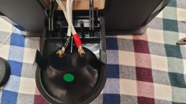
Are you certain the modified speaker is sealed as tightly after opening it as it was originally?
Yes. I even added new sealing gaskets to the speaker mounting points.Are you certain the modified speaker is sealed as tightly after opening it as it was originally?
If you modified the mechanical connection to the cabinet it could have changed the conducted cabinet radiation.
I was thinking about this too. Because I separated the crossovers for each frequency path. In this case, did I also cut off the signal exchange between them? The mid and bass crossovers are at the bottom of the cabinet, only the tweeter crossover is on the top.If you modified the mechanical connection to the cabinet it could have changed the conducted cabinet radiation.
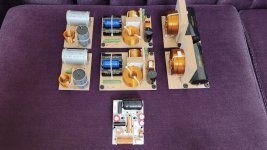
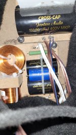
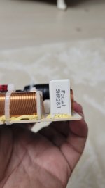
I am adding the pictures of the crossover I made.
Attachments
When I said conducted, I meant through the cabinet panels. I was not talking about electricity.did I also cut off the signal exchange between them?
The crossover interaction is very minor. It's difficult to say whether it had an effect.
The material I used is the product in this link.Depending on the "membrane" material > I would say YES.
https://www.izoyapimarket.com/urun/btm-bituself-star-aluminyum-folyolu-su-ve-ses-yalitim-bandi
The OP stated before that if he placed back the old filter the bass response was stronger. So it seems unlikely that cabinet modifications had any influence.
BUT... first it was that ONLY the filter components were upgraded for higher value components. The OP assured it was a 1:1 swap for higher quality components.
In the mean time we learned that the filter PCB also was replaced by 3 separate PCBs. On the 3 separate PCBs I count 13 components while on the old PCB I count 12.
And still is it a 1:1 component swap. And a schematic is definitely not necessary.
I wonder what the next update is. The woofer was replaced as well?
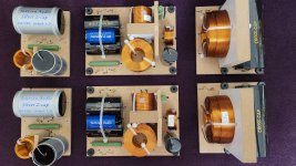
The original crossover circuit also has 13 components. There is a resistor placed vertically in the bottom corner. I think you missed that.In the mean time we learned that the filter PCB also was replaced by 3 separate PCBs. On the 3 separate PCBs I count 13 components while on the old PCB I count 12.
Attachments
- Home
- Design & Build
- Electronic Design
- Focal Vestia No.4 Crossover Upgrade Help Please