Yes i understand that, I can't find any transformer diagram for this model, but just went with the wiring instructions in the service manual and shifted the spade terminals around according to the directions.I hope you understand that when wiring two separate 120volt windings in series, you have to get the 'phase orientation' correct.
Seems to work OK.

Safety feature, when it blows, it makes certain that when a musician replaces the blown external fuse with a larger value (or some tin foil..) it doesn't burn everything up/down!Have rewired for 230V and working sweet, so is a good success story that all hope is not lost in these situations.
Kind of strange that this fuse was on the board with no external fuse holder, huge inconvenience should it blow.
Reminds me of a hotel sound gig where a second shift electrician disconnected our power distribution system after we left thinking we were loading out in the morning, later rechecked the schedule and realized we were still booked for a second night.
He hooked the power back up before we came back the next day...
We always carefully checked our power to make sure the electrician had initially tapped in correctly, but being the second day, we didn't re-check it before flipping the 100 amp mains breaker back on.
PopPopPopPop...
When he re-connected our power tails, the electrician had swapped one of the two hot wires with the neutral, so all the equipment which was left in the "on" position (about 24 different rack units and mains and monitor console PSUs) received 240 volts instead of 120 volts when the mains were flipped on.
The flash of LEDs, noise and burnt smell made a power problem obvious, so the mains were killed before we had turned on any amplifiers.
Corrected the miswire and replaced the FOH and monitor equipment (lucky we had another rig available only 45 minutes away) and the second night's show went OK.
Our tech found most all the fuses blown, but most of the gear worked OK after replacing them.
The electrician had logged his "work", so we were able to get the hotel to pay for the repair/replacement costs.
Anyway, happy for you nothing was charred!
Art
Good for you that the amp is workinh again.
But, again some rules with good intentions:
Did you test the transformer on its own?
Do not test it with all the rest of the electronics connected to it. Never ever do that in this case.
If all is good, test the different dc voltages WITHOUT the Power tubes.
You might have a blown power supply - capacitors, diodes etc...
All reasonable ok? Plug in the power tubes AND a load (speaker or resistor) Set all volume, gain and tone potmeters to a very low setting.
Insert a signal (guitar) and try if there is any sound at the output.
Do not crank the amp open.
Leave it on for some time (5 minutes or more) without an input signal.
Check the bias etc.
Leave it iddle for another 10 minutes.
Check the bias again.
Now you can test the amp with various output levels.
After 15 - 30minutes, recheck the bias.
If all stays stable; the amp is ok.
An SVT needs a carefull biassing to make it reliable.
Yeah the second fuse is likely a second safety measure, its also a slow blow type.
Kind of odd that it's labeled as a filament fuse, when it actually is virtually a second fuse in series.
I couldn't easily remove all the secondary to isolate it, but was possible to measure the HT voltages from the bottom of the tube sockets once running, so I figured using the variac first on a low voltage would be enough to show anything major up without catastrophe, can't get much more worse than where I was to begin with so nothing to loose.
All the primary windings tested OK and the bridge rectifier, etc.
The bias is still looking good on the tubes and behaving normally.
I had left it on for an hour and played a guitar through it on and off, slowly increasing power.
Can you tell me what voltage you get on the power transformer secondary please.
And what DC voltage goes to the output transformer.
(I recently picked up a big power transformer and I am wondering what amp it could be used for. Maybe an SVT alike)
And what DC voltage goes to the output transformer.
(I recently picked up a big power transformer and I am wondering what amp it could be used for. Maybe an SVT alike)
I dont have it on hand anymore to look at that, but the plate voltages were over 650V, the tubes voltage on these things run pretty high.
Well so far it appears the transformer(s) are OK!
There was a "filament" fuse inside that had blown which is a bit unclear to me as it appears to be a power fuse in line with the rest of the supply according to the schematic. The transformer was reading open circuit as a result, but the windings appear all OK.
The 2 primary windings are connected in parallel from what I can gather and there is a second transformer for the filament supply.
The power transformer reads about 6 ohms on the primary and the filament transformer is 16 ohms on the primary.
I connected my variac to it and fired up.
No fireworks reported or fuse blowing which is a good sign, the heater filaments started to glow too.
The good news is that it should be possible to reconfigure this unit for 230V.
All I need to do is rewire the primaries on both transformers in series as per the service manual.
You have been very lucky ! Be careful : the voltages to the plates of the 6x6550 tubers is circa 650-700VDC... More than the usual 450-470VDC of the guitar amps !
I have seen many SVTs coming in in for service or repair. From Top to Bottom :
- vintage 1972 "USA Rolling Stones Tour".
- US-made SVT Classic.
- Vietnam-made SVT Classic.
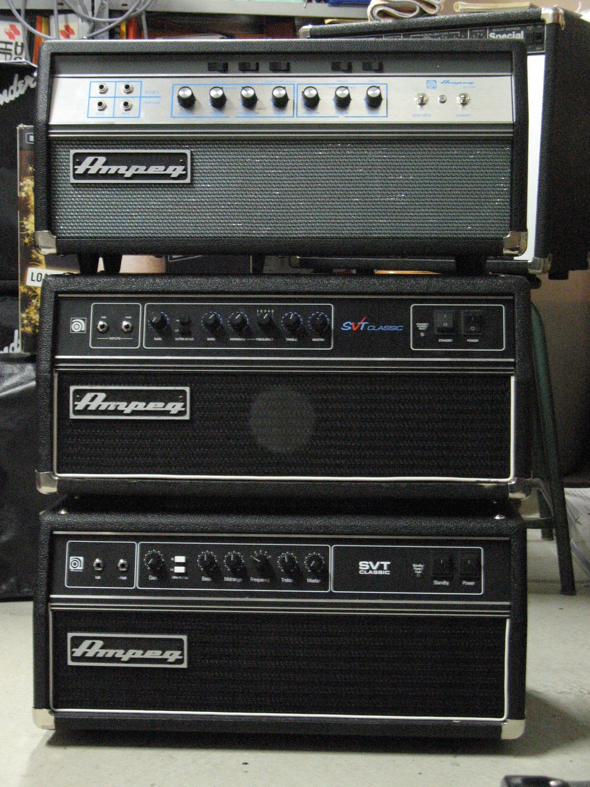
The second and third are good, the first is the best by far, and nearly foolproof !
T
The secondary of my unidentified junkyard transformer is currently measuring 640-0-640 Vac @ 100 mA. I guess I won't be using it in a practice amp.
Wow, 640V AC on that transformer will give you well over 700V DC.
Would probably suit an amplifier using Eimac transmitter tubes or something else exotic.
The hard part is finding capacitors rated at those voltages particularly the electrolytic filter caps for the power supply.
Would probably suit an amplifier using Eimac transmitter tubes or something else exotic.
The hard part is finding capacitors rated at those voltages particularly the electrolytic filter caps for the power supply.
Here is the schematic of the power amp section of a Vintage ampeg SVT (1971) :

I was wrong : it's 695VDC at the CT of the output transformer (point A).
A well restored, top notch setup'ed Vintage SVT will be able put out at least 400W RMS undistorted on a 4ohms rated load... At 40Hz ! A beast...
T
I was wrong : it's 695VDC at the CT of the output transformer (point A).
A well restored, top notch setup'ed Vintage SVT will be able put out at least 400W RMS undistorted on a 4ohms rated load... At 40Hz ! A beast...
T
That's quite a beast, that schematic is much more helpful for the older model than the newer one I was working with too, doesn't show anywhere on mine the primary and secondary configuration like that does.
My schematic does indicate 650V but I believe that's under load, and idle it's supposed to be closer to 700V
My schematic does indicate 650V but I believe that's under load, and idle it's supposed to be closer to 700V
That's quite a beast, that schematic is much more helpful for the older model than the newer one I was working with too, doesn't show anywhere on mine the primary and secondary configuration like that does.
My schematic does indicate 650V but I believe that's under load, and idle it's supposed to be closer to 700V
Yes, the reissues of the SVT - called SVT Classic - are definetly Nuclear Plants, full of solid-state components, regulators, timers, bias controllers, fuses here and there, etc... That tend to burn at the first occasion. All the SVT Classic that I had for repair had flaws in their ancillary solid-state circuits ! The Vintage ones do not suffer all those ancillary problems : simpler is much better... Just like their schematic drawings !
T
Wow, three power transformers in this boat anchor! Those wo had to lift that piece of gear on top of the 8 x 10 speaker cabinet must have suffered from severe backache...
Best regards!
Best regards!
My HP3585A spectrum analyzer has handles, but that does not necessarily mean that it is portable (40kg, 88lbs).
Yes I tend to avoid touching that sort of gear, such a nightmare to work on, thankfully this unit had very little extra added to the signal path, it was more extra support circuitry for protection and effects loops etc.Yes, the reissues of the SVT - called SVT Classic - are definetly Nuclear Plants, full of solid-state components, regulators, timers, bias controllers, fuses here and there, etc... That tend to burn at the first occasion. All the SVT Classic that I had for repair had flaws in their ancillary solid-state circuits ! The Vintage ones do not suffer all those ancillary problems : simpler is much better... Just like their schematic drawings !
I once worked for a fella who repaired this sort of equipment for people and he had this faulty fender "reissue" amp come in and it's far from a reissue, it just has the same looking cabinet, that's all.
He was looking at this thing all day before he isolated the fault down to some obscure little IC, the schematic was huge and unfolded to cover the whole workbench.
You could hardly call this a tube amp, there was a ton of solid state components, ICs, transistors etc all over the PCB.
People often don't know the difference between a tube amp and what I like to call a "pure" tube amp, they don't fully get it until I show them what's inside, ironically you end up paying more for less to get just this with a handwired amp.
Tube amp should just mean that, tubes only with perhaps an exception to a rectifier.
Yeah its pretty darn heavy, I barely managed to place it on my workbench and getting out the heavy chassis is not much easier.Wow, three power transformers in this boat anchor! Those wo had to lift that piece of gear on top of the 8 x 10 speaker cabinet must have suffered from severe backache...
Best regards!
My marshall clone using 807 output tubes isn't much lighter either, it has a whopping big output transformer.
Wow, three power transformers in this boat anchor! Those wo had to lift that piece of gear on top of the 8 x 10 speaker cabinet must have suffered from severe backache...
Best regards!
The 1972 SVT head weights 45.0kg. Yes, it's an Anvil !
The others are a bit lighter, but it is at the detriment of reliability...
T
- Home
- Live Sound
- Instruments and Amps
- Ampeg SVT Classic amplifier 120V model connected to 230V mains, what damage is likely?