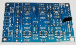
Hi.I asked seller but he did not respond. Is this board 12db/oct or 24db/oct ? And it seems there is 7 resistors and 8caps. Should not they be same quantity?
I will use them for 225Hz. So is it ok to use 33K dale cmf55 and 15nF kp1830 1% capacitors?
It writes these information on his ebay page
crossover point formula:F=0.707/(2x3.14RC)
sample :
C=1nF R=22K F=0.707/(2*3.14*22000*0.000000001)=5117HZ=5KHZ
C=1nF,f=4.7kHz,R=24k
C=1nF,f=4.4kHz,R=25.6k
C=1.5nF,f=4.1kHz,R=18.3k
C=1.5nF,f=3.8kHz,R=19.7k
C=1.5nF,f=3.5kHz,R=21.4k
C=1.5nF,f=3.2kHz,R=23.5k
C=2.2nF,f=3kHz,R=17k
C=2.2nF,f=2.8kHz,R=18.3k
C=2.2nF,f=2.5kHz,R=20.5k
C=2.2nF,f=2.2kHz,R=23.3k
C=2.7nF,f=2.2kHz,R=19k
C=2.7nF,f=2kHz时,R=20.8k
C=3.3nF,f=1.8kHz,R=19k
C=3.3nF,f=1.5kHz,R=22.7k
C=4.7nF,f=1.3kHz,R=18.4k
C=4.7nF,f=1kHz,R=24k
C=6.8nF,f=1kHz,R=16.6k
C=6.8nF,f=900Hz,R=18.4k
C=6.8nF,f=800Hz,R=20.7k
C=6.8nF,f=700kHz,R=23.6k
C=10nF,f=700Hz,R=16.1k
C=10nF,f=600Hz,R=18.8k
C=10nF,f=500Hz,R=22k
Attachments


That’s not correct. It should be 1/…, but that’s for a single pole. For multiple poles it’s complex ;-)F=0.707/(2x3.14RC)
Only solution is measuring with oscilloscope right? I bought it many years ago and will use them for FAST project.C-C about 40cm between drivers.
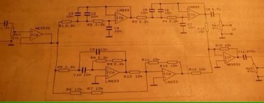
Derived from the photo by "connecting the dots". 99+ % sure it is correct, it does simulate properly.

@Veysel calculated values do produce 225Hz :

LTSpice sim attached
@Veysel calculated values do produce 225Hz :
LTSpice sim attached
Attachments
Thank you for your effort.Is it hybrid or same as LR 24db oct? Why he did such a board? I did not understand it completely.
I don't know about "hybrid", but it is 24dB/oct. Strictly speaking, it is not LR. Phase is different than LR:
LR is 0º AT the crossover frequency, this board is -180º, otherwise essentially the same.
Who knows why this design was devised, perhaps for a special need and/or specific drivers. As I said before, it's an unusual circuit, I've never seen the like before.
LR is 0º AT the crossover frequency, this board is -180º, otherwise essentially the same.
Who knows why this design was devised, perhaps for a special need and/or specific drivers. As I said before, it's an unusual circuit, I've never seen the like before.
Hi.Here is same schematic i think.
https://tr.aliexpress.com/item/33009712814.html?gatewayAdapt=glo2tur
https://tr.aliexpress.com/item/33009712814.html?gatewayAdapt=glo2tur
Derived from the photo by "connecting the dots". 99+ % sure it is correct, it does simulate properly.
View attachment 1419923
@Veysel calculated values do produce 225Hz :
View attachment 1419924
LTSpice sim attached
How can we determine the optimal component values for active crossovers? For example, which combination would be better: 33kΩ with 15nF or 10.5kΩ with 47nF for 225Hz? What are the practical limits for these values? Can we use something like 3.3kΩ with 150nF? What impact do these choices have on circuit performance?
Attachments
Hi, I meant 10,500, not 19,500. Based on the seller’s formula, the cutoff frequency is calculated as:
fc=0.7072×3.14×10,500×47×10−9f_c = \frac{0.707}{2 \times 3.14 \times 10,500 \times 47 \times 10^{-9}}fc=2×3.14×10,500×47×10−90.707
which results in 225 Hz.
I’m curious about the effects of doubling the resistor value while proportionally reducing the capacitor. How does this impact circuit performance in terms of noise, impedance, and overall behavior? Would there be any noticeable trade-offs?
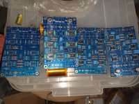
And here the boards.The 2 left side ones for Fast system. I replaced the resistors of the boards. It was 19k1 and i increased them to 33K to make 225Hz.Capacitors are 15nF. (dale cmf55 resistors was marked as 5% but i measured them with DER EE LCR meter and they are usually between 0,25% surprisingly)
Attachments
It changes the Q, which you don’t want.I’m curious about the effects of doubling the resistor value while proportionally reducing the capacitor.
The seller’s formula only applies to 2-pole Sallen-Key filters with Q=0.707, i.e. Butterworth. That’s the HP part of this circuit. The LP part is different, with different equations.
This crossover is the one described on p135 of Doug Self, The Design of Active Crossovers, the chapter Subtractive Crossovers.
It consists of:
1. Two Sallen & Key 2-pole Butterworth HP filters, which therefore constitute a 4th order Linkwitz-Riley HP filter.
2. An MFB allpass delay filter, summed with the inverse of (1), which turns it into a 4th order L-R LP. The delay is necessary to correct the subtracted response.
Self states that subtractive crossovers are extremely sensitive to component tolerances.
Abandoned My 24dB/Oct Linkwitz-Riley Crossover Build – Looking for a Better Solution
Hey everyone,
I recently started assembling a 24dB/oct Linkwitz-Riley crossover using a pre-designed PCB, thinking it would be a great solution. I had four boards partially built, but after reading more—especially from sound-au.com—I realized that this design might not be as good as I initially thought.
It turns out that many so-called Linkwitz-Riley crossovers aren’t truly ideal and can have issues with phase response, accuracy, and real-world performance. After learning this, my motivation dropped, and I decided to stop assembling the boards rather than continue with a design that might not perform well.
Now, we’re planning to build a proper 24dB/oct Linkwitz-Riley crossover, making sure it follows the correct principles for the best performance. If anyone has experience with high-quality active crossovers or recommendations for a well-designed board, I’d love to hear your thoughts!
Looking forward to discussing this with you all.
What do you mean.. is it when you combine them with the imperfect response of the speaker, the result is not Linkwitz Riley?so-called Linkwitz-Riley crossovers aren’t truly ideal and can have issues with phase response, accuracy, and real-world performance.
Why not compensate the differences another way. You can change the frequency and Q factor of your active section, or even the slopes if necessary. You can then manage peaks and dips another way, maybe with active filters or even at speaker level.
It just means you'll have to design your crossover using similar techniques that others use when they measure and simulate.
It would make more sense to publish the design here, so we can tell you whether ur not it is ‘proper’, and if not how to fix it.and I decided to stop assembling the boards rather than continue with a design that might not perform well
If it isn’t ideal in the respects you mention it isn’t a Linkwitz-Riley crossover at all.
Upon reviewing the information on the Sound au website, it appears that subtractive crossovers may exhibit performance issues. Notably, some PCBs sold from China, advertised as Linkwitz-Riley 24dB/octave crossovers, are actually subtractive crossovers, which could lead to suboptimal performance. To ensure accurate results, I plan to build a genuine Linkwitz-Riley filter as detailed on the Sound au website.
I'm using ChatGPT to refine my wording and make it clearer. I hope there's no misunderstanding. Let me know if anything needs further clarification! 😊
I'm using ChatGPT to refine my wording and make it clearer. I hope there's no misunderstanding. Let me know if anything needs further clarification! 😊
- Home
- Source & Line
- Analog Line Level
- Is this crossover board 12dB/oct or 24dB/oct