In my opinion the NJM4580 as an op amp can limit high frequency response and dynamics, especially in audio applications.
The input buffer will be the biggest contribution to distortion and I don't see a need for it as the input impedance of an op-amp should be sufficiently high.
Why not just use a more powerful op-amp? or use a current buffer, such as your 'opamp driven diamond buffer amplifier' thread?
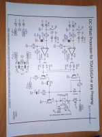
There is a good example from https://www.sound-au.com/project113.htm:

Why not just use a more powerful op-amp? or use a current buffer, such as your 'opamp driven diamond buffer amplifier' thread?
There is a good example from https://www.sound-au.com/project113.htm:

the buffer was supposed to isolate the potentiometer but the source device im going to use should be ok on its own, my point is to drive things like iems and higher impedance headphones from everything including phones computers cd and dvd players or maybe in the future vinyl. my other idea was to use the sip package to make it into a stick of some sorts.
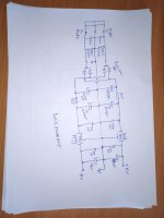
i also made up this circuit but its kinda pointlessThe input buffer will be the biggest contribution to distortion and I don't see a need for it as the input impedance of an op-amp should be sufficiently high.
Why not just use a more powerful op-amp? or use a current buffer, such as your 'opamp driven diamond buffer amplifier' thread?
There is a good example from https://www.sound-au.com/project113.htm:
View attachment 1421014
Not pointless at all, single ended class A output stage for high impedance headphone usage! although R3 looks pointless to me, gain and idle current looks a bit high...
It all depends on the set of criteria your after. Are you simulating and experimenting for fun? or actually want to build something to use?
It all depends on the set of criteria your after. Are you simulating and experimenting for fun? or actually want to build something to use?
This looks like a good 'base' topology to work with and possibly build multiple variations of.
100s of hours of simulations are possible, but a better idea may be 100s of hours of practical experiments (many of which I have NOT done, btw, but I consider the ideas valuable enough to keep them on my must-do list.) E.g.:
Compare different CCS' -- single transistor vs 2, or adding a cascode.
Resistor loading, and/or choke loading instead of a CCS. Does an air-cored choke sound different from a choke using powdered iron or solid steel?
Feedback experiments: trying a grounded current-sense resistor. A DC blocking capacitor could be added if there is a DC offset. Look up mixed-mode feedback and current feedback.
Output transistor: do different transistors actually sound different, as some have claimed in the past? What about running the transistor in open collector mode, or open drain (MOSFETs)? In fact, just changing R2 could be interesting, as well as R7.
DC coupling experiments: connect a 6V battery to the HP's common ground, fine tune R7 so the output voltage is exactly equal, and then bypass C4.
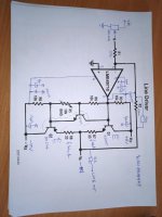
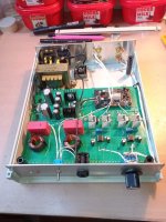
I made this for a friend, i.e. modified an existing headamp. I used a box, a transformer and some small parts. It sounds great to me, and it's not expensive. The schematic is an inverting amplifier, but it can be noninverting, and any opamp. Transistors can be all BD139/140, or some others. I used BD235/236 because I have a lot of them paired. Quiescent current is 30mA, it can be higher if the heatsinks and transformer are increased. The large coils and the red caps are the AKG K371 correction filter, just ignore it. The snubber on the secondaries is determined by the Quasimodo tester, it should be thrown out because it does not fit any other transformer.
Attachments
Last edited:
Some people are just too broke for chokes and fancy doo dadsThis looks like a good 'base' topology to work with and possibly build multiple variations of.
100s of hours of simulations are possible, but a better idea may be 100s of hours of practical experiments (many of which I have NOT done, btw, but I consider the ideas valuable enough to keep them on my must-do list.) E.g.:
Compare different CCS' -- single transistor vs 2, or adding a cascode.
Resistor loading, and/or choke loading instead of a CCS. Does an air-cored choke sound different from a choke using powdered iron or solid steel?
Feedback experiments: trying a grounded current-sense resistor. A DC blocking capacitor could be added if there is a DC offset. Look up mixed-mode feedback and current feedback.
Output transistor: do different transistors actually sound different, as some have claimed in the past? What about running the transistor in open collector mode, or open drain (MOSFETs)? In fact, just changing R2 could be interesting, as well as R7.
DC coupling experiments: connect a 6V battery to the HP's common ground, fine tune R7 so the output voltage is exactly equal, and then bypass C4.
either that the omicron or other basic boosted ab op amps. it may be the best option there is.The input buffer will be the biggest contribution to distortion and I don't see a need for it as the input impedance of an op-amp should be sufficiently high.
Why not just use a more powerful op-amp? or use a current buffer, such as your 'opamp driven diamond buffer amplifier' thread?
There is a good example from https://www.sound-au.com/project113.htm:
View attachment 1421014
i have a bunch of probably to spec bd139's from aliexpress and an 2x15V sealed transformer from a booster bag detector i found in the bin
Did the salvaged sony mini system have a power supply?Some people are just too broke for chokes and fancy doo dads
as generic as it gets although i would add an relay to switch between 100 ohm and 10 ohm emitter resistors
http://nwavguy.blogspot.com/2011/07/cmoy-with-gain.html
Lots of info, search objective 2 headphones amp on diyaudio
Lots of info, search objective 2 headphones amp on diyaudio
i think i should first make up an potentiometer/headphone jack board since all my headphone jacks are dead
plenty of designs i know but i dont care much about ithttp://nwavguy.blogspot.com/2011/07/cmoy-with-gain.html
Lots of info, search objective 2 headphones amp on diyaudio
- Home
- Amplifiers
- Headphone Systems
- headphone amplifier design