Hi Wparks
I bought the excell software at the link https://www.delatsch.com/. There is all kinds of information in this calculation program. It is very useful for me. There is also a lot of technical information. I also do not wind the transformers by hand. I give all the technical information to my transformer. Professionals wind them.
I bought the excell software at the link https://www.delatsch.com/. There is all kinds of information in this calculation program. It is very useful for me. There is also a lot of technical information. I also do not wind the transformers by hand. I give all the technical information to my transformer. Professionals wind them.
What is not shown is the "start" and "end" of the windings. From these, we can know whether or not the transformer, as it is connected, inverts signal polarity or not, and therefor if the feedback loop makes positive or negative feedback. For the feedback to be negative, signal voltage at the output needs to be the same polarity as the signal at the input jack.Below are the technical specifications of my output transformer.
So, the pentode stage inverts polarity, the split-load driver inverts polarity to V2 grid, and V2 inverts polarity to the Red primary winding. That's three inversions, an odd number, so the Red terminal is the wrong polarity for negative feedback if it is the same "end" or "start" as the marked 6 Ohm terminal. Does that make sense? Try swapping polarities, as grovergardner suggested, and don't panic.
All good fortune,
Chris
Hello, first of all, thanks to everyone who is interested and offering help. I am working on this project with my friend Fazıl. Let me summarize the situation: We tried various changes related to polarity. The direction of polarity is clearly visible in the transformer windings anyway. The 8 Ohm load was tested flawlessly and without issues for a long time. For the 4 Ohm load, various experiments and modifications were made. Polarity was tested, and negative feedback connections were removed, but the issue remained unresolved. As a result, we returned to the 8 Ohm configuration. This time, one of the ECF80 tubes failed. Whichever channel I plug the tube into, I get a sharp, high-frequency looped sound from that channel, as if it were connected with reverse polarity.
What’s even more interesting is that when I power the amp with a dim bulb tester, the seemingly problematic ECF80 tubes in both channels work fine. Of course, since it’s not running at full power, the sound quality isn’t great. Below, I’m attaching the video link of the amp working on 8 Ohms before one of the channels failed. The sound quality was excellent, and there was no background noise at all.
What’s even more interesting is that when I power the amp with a dim bulb tester, the seemingly problematic ECF80 tubes in both channels work fine. Of course, since it’s not running at full power, the sound quality isn’t great. Below, I’m attaching the video link of the amp working on 8 Ohms before one of the channels failed. The sound quality was excellent, and there was no background noise at all.

Hi Chris,What is not shown is the "start" and "end" of the windings. From these, we can know whether or not the transformer, as it is connected, inverts signal polarity or not, and therefor if the feedback loop makes positive or negative feedback. For the feedback to be negative, signal voltage at the output needs to be the same polarity as the signal at the input jack.
So, the pentode stage inverts polarity, the split-load driver inverts polarity to V2 grid, and V2 inverts polarity to the Red primary winding. That's three inversions, an odd number, so the Red terminal is the wrong polarity for negative feedback if it is the same "end" or "start" as the marked 6 Ohm terminal. Does that make sense? Try swapping polarities, as grovergardner suggested, and don't panic.
All good fortune,
Chris
Is the start and end shape in the diagram below appropriate.
Attachments
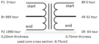
In this diagram, P1 is plate of V3 and P2 is plate of V2.Is the start and end shape in the diagram below appropriate
All good fortune,
Chris
ps: note that a 4 Ohm tap does not use half the turns of an 8 Ohm tap
Hi Chris,
I have one last question,
I read that the center of the secondary side would be 4 ohms. You say not exactly in the half. How can I calculate it. Can you help me.
I have one last question,
I read that the center of the secondary side would be 4 ohms. You say not exactly in the half. How can I calculate it. Can you help me.
E = sqrt PR and E varies linearly with turns, so turns, for the same power, varies with the sqrt R. For example, if the 8 Ohm tap is 100% of the secondary turns, then the 4 Ohm tap is sqrt (4/8) = 70.7% of secondary turns, and half of turns is a 2 Ohm tap.
All good fortune,
Chris
All good fortune,
Chris
Yes. In both, voltages vary linearly with turns and impedances vary by sqrt of turns.
All good fortune,
Chris
All good fortune,
Chris
To try & find the fault, you/we need more data, I think we need to step back a bit. When i build an amp for the first time I check, re-check & double re-check my work. One wire not connected, one solder joint not right, your buggered.So, check the DC conditions of the amp first. Write it all down.
Next apply a 1khz sine wave with no NFB and take notes again, EG AC at IP, V1 anode, V2 IP/grid etc. Then apply NFB with 8r load, take notes. Same for 4r load.
Next substitute the NFB resistor for a 20-50k pot, 10 turn precision if possible, wired as a variable resistor, set it 50k. Reduce R till nasty HF starts, again noting AC voltages.
If you have no scope but do have a PC, download Soundcard scope then make a 10:1 attenuator so you can test your amp. Soundcard scope is easy to use & setup, it has a scope, sig gen, fft & THD meter as well as recording frequency.
Then you'll have more information to solve your problem, at the moment you are blind. Good luck, Andy.
- Home
- Amplifiers
- Tubes / Valves
- Tube Amplifier Audio feedback high-pitched noise continuous loop