That is the kind of droopy roll-off i suggested. You can see the ripple, it would be worse without mass-loading.
dave
dave
Thanks all, this has been super helpful and rewarding.
I was scratching my head thinking about why a Voigt pipe would not be conical, as it looks similar to a conical horn in x-section. However, after thinking for a bit I realised that in 3D it's not actually the case. As far as I can tell, a conical horn which doubles in diameter over a given distance will quadruple in area, whereas a Voigt Pipe which doubles in width over the same distance is only doubling in area. Right? I think I get why I have to use the parabolic horn now!
Using a parabolic horn and the correct path length really cleaned it up and I was able to drop the total length to 180cm and get the below response. Thanks @David McBean for taking the time to assist with the great tool you have provided! Hopefully this roll off is more in line with your preferences @planet10.
Very tempted to build to the current dimensions and tune with stuffing and see how I go.

As far as I can tell, a conical horn which doubles in diameter over a given distance will quadruple in area, whereas a Voigt Pipe which doubles in width over the same distance is only doubling in area. Right? I think I get why I have to use the parabolic horn now!
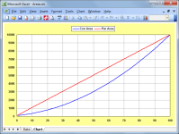
The flare profile designation is based on how the radius of an axisymmetric horn changes with axial length, not on how the cross-sectional area changes. Your Voigt pipe design has two parallel sides and two sloping sides, meaning that the cross-sectional area expands linearly with axial length. The cross-sectional area of an axisymmetric parabolic horn also expands linearly with axial length. The attached chart compares the cross-sectional area versus axial length of a conical horn against that of a parabolic horn, each having S1 = 100, S2 = 10000 and L12 = 100.
Attachments
Hi All,
After messing around in Hornresp a fair bit, I think I will pursue a 1.8m long taper with the driver mounted halfway down the baffle, as per the below pic. While I could make a traditional unfolded design, a folded design is appealing for the reduced space and also because I can fit the panels on a CNC machine I have access to. I'm interested to know if you think the folded design to the right is a "close enough" approximation to the design on the left. It seems difficult to simulate accurately so I am tempted to just build it and see.
Also, regarding the Hornresp snapshot below, is there a simple way to estimate the required stuffing in terms of kg of polyfill?
Your advice is appreciated!
Greg
See help under LS Wiz:
"When the Schematic and Filling options are selected, the total volume of
filling material in the system is shown in litres. If all airflow
resistivity values are less than 1000 mks rayls/m then the total weight of
Polyfill absorbent material in kilograms required to achieve the specified
resistivity is also shown. Double-clicking on the Filling label switches
between total and segment values."
Re folding, to find the correct board length/offset, need to calculate its axial length (down the middle), then do the fold per the 71.4 cm axial bend. That said, the amount of damping required for simple ~ full range pipes renders it moot, so only useful for H.E. wide range (sub) woofer pipe horns.

Last edited by a moderator:
@grindstone ahhhh, thanks now I see what's happened - too much stuffing made the kg readout disappear. I knew I had seen it previously but couldn't figure out why I had lost it. Thanks!
@GM Sorry, can you explain this a little more? I don't quite understand what to do with this diagram. Thank you!
@GM Sorry, can you explain this a little more? I don't quite understand what to do with this diagram. Thank you!
I think GM is saying something like this:
In order to calculate the correct driver position along the length of the folded line, you need an accurate way to measure the center-line as it rounds the bend. There are different ways to measure, and GM is giving you the one that is the most accurate.
Otherwise, you might end up positioning the driver at a less optimal position (you're trying to nail the cancellation of a certain harmonic - if you don't nail it, you would just have to use more stuffing but then the overall output is reduced.)
I'm a skilled woodworker but lacking the requisite math skills, I was hoping to see the final results of this thread as in somebody actually building the Voigt Pipe speaker and publishing the results. Oh, well. I'm not giving up just yet. I have a pair of Tang Band W8-1808. Now, if I could only I find the plans for a nice Voigt Pipe speakers...
No math skills required, just draw it out to scale same as for any ~complex woodworking, etc. project.
...and one of the worst that I've seen. 😉 Okay, that's unfair -it could be [significantly] worse. But it's not fantastic either IIRC, although it's been a few years since I last sat through it, so I can't remember everything that was covered & I don't have time right now to watch it again.
I'm sure I've done one of these for the 1808 before, but for whatever it's worth, & keeping size down to the [roughly] Vb = Vas that's about the minimum realistic for this unit, one ML-Voigt would be:
Internal dimensions
L = 72in
W = 10in
D = 15in (at base)
Zd = 36in
Zv = 68in
Dv = 3in
Lv = 1.5in
Fb = 36Hz
F6 = 36Hz [nominal anechoic]
Where Zd = driver tap location from the throat, Zv = vent distance from the throat, Dv = cylindrical duct diameter, Lv = duct length, Fb = box tuning, F6 = -6dB frequency under 1/2 space assumptions.
Lag the back & one sidewall with 1in OC-703 rigid acoustic fibreglass or an equivalent 3lbs/ft^3 rated type, 1in SAE F10 rated wool felt or 1in - 1.5in recycled denim. Avoid acoustic foam if possible -it doesn't do much. Adjust as preferred. Build material can be whatever you want, although I'd be looking at 3/4in Baltic birch ply as a minimum, preferably with a doubled front baffle. If you want to go the full Cain, solid tight-grained 3/4in sealed maple, or 3/4in tight-grained alder for the front & side baffles with 3/4in particleboard for the rear panel. Slightly tickled gain through the midbass, relatively well damped rolloff. You can get lower with more output, but the price is a larger box with higher excursion.
As a minor addition, which I'd meant to include in the above, if you want to raise Fb to Fs for a classic symmetric alignment with a bit more gain through the midbass, duct diameter increases to 4.5in.
robably this is the best guide I' ve seen:
Not that crap video again. Lots of misinformation. You have to know morenthan this guy to know where is is correct and more imnportant where he is out to lunch.
dave
+1 I thought it looked familiar. That said, during that time Bob (I forget his last name) among other designs did one that folks liked, so wondering if his long gone website is on the net archive.
I'm sure I've done one of these for the 1808 before, but for whatever it's worth, & keeping size down to the [roughly] Vb = Vas that's about the minimum realistic for this unit, one ML-Voigt would be:
First pass/free Festival: http://wodendesign.com/downloads/1808-ML-Voigt-0v8-050225.pdf
dave
Would you name some of the important misinformation?
You are not going to make me waste time watching it again are you? Not gonna happen.
dave
Ye gods, that was quick. 😉
Nice work, Dave! 🙂
thanks a lot for publishing these plans. This will keep me busy for a few days...First pass/free Festival: http://wodendesign.com/downloads/1808-ML-Voigt-0v8-050225.pdf
View attachment 1417620
dave
Greetings from Sydney
I just posted about full range drivers and some art stuff Im doing atm. Of course the art is secondary but creating a solid seque between form and function, I was just reading responses to the Voight pipe topic and realise the stylized tusk may be applicable. Im in no way constrained to wood and planar design.
My question is, because the internal volumes of what I do can be different to the outside appearance, and there is mention of parabolic relationships in the horn, do you think its possible to adapt eg design by @planet10 to an organically shaped output?
I would also ask if there is anything that could be improved, can a floor firing aperture be incorporated...
Thanks for any help
EDIT: Also, if the vertical cross section is no longer rectangular, then rear path summing with the direct radiating output of the driver is going to be reduced ie reduce nulls because there are no planar facings? Or as I have found with the sphericals I mentioned, they use tapered fusiform and the effect ie reductions is very noticeable in AB to normal golden ration box designs
Last edited:
- Home
- Loudspeakers
- Full Range
- Voigt Pipe Design