
Both interesting and confusing . . .
What’s going on with the OT primary? It apparently has no voltage going through it. At the top the two versions show different (AC?) voltages but both ends are grounded with the other side going to ground through a 100Ω resistor?
Good to see some interest in the 6N6G, though. This is the actual schematic for what was built. It’s similar, but not exactly the same as what someone asked you about.

I didn’t use any global NFB. Instead, I used one of your earlier suggestions and tied the plates of both sections of the 6N6G together. This tightens up the bass and the output drops a bit. Since this is what we expect to hear when feedback is used I assume this produces some local NFB. Bass is solid to the ear so I didn’t feel the need to experiment with any additional NFB.
This was a project that I did this past summer with my 10 year old granddaughter. I drilled a few of the larger holes in the chassis but she did everything else herself. She uses it in her bedroom with a pair of small Polk bookshelf speakers.
Some pics:


Here’s the build thread:
https://audiokarma.org/forums/index...-old-granddaughter-builds-a-tube-amp.1066126/
What’s going on with the OT primary? It apparently has no voltage going through it. At the top the two versions show different (AC?) voltages but both ends are grounded with the other side going to ground through a 100Ω resistor?
Good to see some interest in the 6N6G, though. This is the actual schematic for what was built. It’s similar, but not exactly the same as what someone asked you about.
I didn’t use any global NFB. Instead, I used one of your earlier suggestions and tied the plates of both sections of the 6N6G together. This tightens up the bass and the output drops a bit. Since this is what we expect to hear when feedback is used I assume this produces some local NFB. Bass is solid to the ear so I didn’t feel the need to experiment with any additional NFB.
This was a project that I did this past summer with my 10 year old granddaughter. I drilled a few of the larger holes in the chassis but she did everything else herself. She uses it in her bedroom with a pair of small Polk bookshelf speakers.
Some pics:
Here’s the build thread:
https://audiokarma.org/forums/index...-old-granddaughter-builds-a-tube-amp.1066126/
Last edited:
For sure that way of drawing a schematic looks odd to many.
But it is very common & is widely used by designers, both toobz & SS.
And combinations of those.
It separates out the biasing & power to the active devices & leaves only the signal part.
Very easy to use for many of us who have been around too long.
The page from Seelys 1958 text book that I used while going thru the mill as here. 🙂 👍
Attachments
Thanks for the explanation. I figured it was something related to the sim process.For sure that way of drawing a schematic looks odd to many. . . . It separates out the biasing & power to the active devices & leaves only the signal part.
I'm quite happy with the the sound using your earlier suggestion of connecting the plates of the 6N6G's sections. Any idea how that measures compared to the method suggested above?
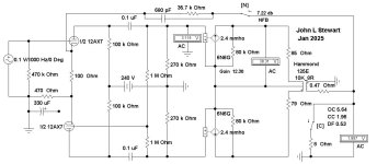
Here is the results of that wiring change you tried.
The reason the amp sounds tighter, the Damping Factor improved from 0.3 to 1.24.
That single change helped to control your speaker.
Send me the primary & secondary OPT resistances, that way a more accurate number is possible.
The numbers I used are simply a best guess, just something to stuff into the Sim to get a result. 🙂👍
Attachments
Thanks, that correlates well with what I hear. I’m afraid I didn’t measure the OT resistances during the construction phase and I no longer have ready access to the finished amp.Here is the results of that wiring change you tried.
The reason the amp sounds tighter, the Damping Factor improved from 0.3 to 1.24.
That single change helped to control your speaker.
Send me the primary & secondary OPT resistances, that way a more accurate number is possible.
The numbers I used are simply a best guess, just something to stuff into the Sim to get a result. 🙂👍
Yeah,my first build using the 6N6G involved modding a Magnavox amp pulled from a console stereo. It originally used 6V6s.I wondered if you had tried PP 6N6G yet?
Here’s the build thread on that one:
https://audiokarma.org/forums/index.php?threads/magnavox-175-185-build-with-a-twist.934198/
It's definitely an ugly duckling but it sounds wonderful. Here's pics:
And here’s the schematic:
OK Charlie & the lurkers, I finally got back on the 6N6G.🙂👍
(Charlie & the Lurkers, kinda rings a bell. Terry & the Pirates, a 50s kids radio serial).
This time I found while looking at the specs for the 6B5, the predecessor of the 6N6G
was intended to replace a 42 in existing circuits. The 42 is the old 6-pin version of the octal 6F6.
So for the calcs we need to be using the 6F6 numbers.
On this 6N6G triode connected version (plates tied together) the DF is much better at 2.15.
Looks pretty much as an SET would be. As usual, much depends on the
OPT primary & secondary resistances.
I'll try a 6N6G PP version next.
Attachments

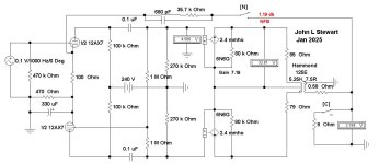
OK Charlie, here is the 6N6G PP version covering the Magnavox 185.
Oddly the originator designed in a NFB connexion, but then pretty much
canceled its effect by adding that 330 microF electrolytic across the 470R
in the front end. Very strange indeed.
So the amp has very poor speaker damping, the NFB would help that.
Something to try in the future.
Tying each of the plates together would make a big difference,
But less power. 👍 👍
Attachments
Thanks for taking a closer look at these.OK Charlie, here is the 6N6G PP version covering the Magnavox 185.
Oddly the originator designed in a NFB connexion, but then pretty much
canceled its effect by adding that 330 microF electrolytic across the 470R
in the front end. Very strange indeed.
So the amp has very poor speaker damping, the NFB would help that.
Something to try in the future.
Tying each of the plates together would make a big difference,
But less power. 👍 👍
The results of tying the plates of 6N6G together on the SE ones can readily be heard.
The portion of the PP schematic that you mention - the 330uf bypass cap across the 470Ω cathode resistor - was something I just copied from the Leben schematic. I just assumed that the input / phase inverter section of a highly praised $3500 Japanese amp would work well even though I’m running 6N6G outputs instead of EL84s.
I arrived at the values used in the GNFB network totally by ear and the bass certainly doesn’t sound sloppy at all. Sometime I’ll put the amp back on the bench and see how it sounds without the cathode bypass cap and/or with the 6N6G plates tied together.
PP 6N6Gs will supposedly put out ~10wpc and I was hoping to approach that as much as possible given the restraints of using this old console amp as a starting point.
According to the 6N6G data sheet, they can also be operated in high power PP which yields 20 wpc. I’d like to try that sometime but I think it would require a ground up build using much better transformers than the ones on the Magnavox.
And 10k PP OTs don’t seem to be common. I actually have a pair of vintage Chicago ones but, despite their size and weight, the Chicago catalog lists them as only being good for 10w. That seems odd because they suggest using 807s as the outputs and most PP 807 designs seem to be, what, 25 to 35 wpc???
24 ohms of resistance no feedback, wow I knew single ended amps were close to current amps but not this much.
The transformer is likely not matched to the tube. Ex. Open circuit 15v and double load current would be a better match.
6k or 8k primaries
The transformer is likely not matched to the tube. Ex. Open circuit 15v and double load current would be a better match.
6k or 8k primaries
I assume you’re commenting on the schematic @jhstewart9 used for his simulation, which I don’t really understand.24 ohms of resistance no feedback, wow I knew single ended amps were close to current amps but not this much.
The transformer is likely not matched to the tube. Ex. Open circuit 15v and double load current would be a better match.
6k or 8k primaries
As for the OT primaries . . . The SE versions I’ve built use a 7k primary which is what is specified in the 6N6G data sheet. His SE sims use 6.8K : 7.5Ω.
The Magnavox PP that I converted to use 6N6Gs uses the stock OTs. As I said in the thread I linked, “In push-pull, the 6N6G wants to see a load of 10k. Using 8 ohm speakers with the stock, 4 ohm, OTs they're seeing a 12K load, according to the Sams. When I measured them I found that they are actually 13K into an 8 ohm load. So not perfect but close enough.”
I just noticed that his PP sim uses a 5.25k : 7.5Ω OT. Not sure how this affects the results. Perhaps he will comment.
I'll run another Sim on the weekend with the 10K PP OPT hookup.
Either way will hardly move the needle on DF, Pentode (& 6N6G) will still be much less than One.
Pentodes are current devices, ie mA per Volt in parallel with their own plate resistance rp.
They need some in cct NFB in order to get any kind of circuit (loudspeaker) damping.
But the whole system may sound OK anyway. 🙂 👍
Both the SE and PP versions I built do use NFB and, subjectively, sound really good.Pentodes are current devices, ie mA per Volt in parallel with their own plate resistance rp.
They need some in cct NFB in order to get any kind of circuit (loudspeaker) damping.
But the whole system may sound OK anyway. 🙂 👍
One of the SE versions does have a switch which allows me to tie the two 6N6G plates together or not. I added that option in case I felt that I needed more power output but I haven’t felt the need and I prefer the sound with the NFB.
As for the PP version, at some point I will try your suggestion and eliminate the 330uf cathode bypass cap on the 5751s in order to make the existing GNFB more effective.
In the Sim putting the bypass cap out of the circuit increases the NFB quite a bit.
The DF increases from a small fraction to somewhat more, still less than one.
But worth having.
In the PP version when each of the 6N6Gs plates are tied together so in cct they
look like a common triode the DF looks a lot better. Some more NFB on the external
path would improve the DF even further. All of the numbers are on the Sims.
As PP 6N6G triodes the audio power is about 3.5 Watts without exceeding
plate dissipation.
Hope all this makes sense.🙂
Attachments

- Home
- Amplifiers
- Tubes / Valves
- half 6SN7 6N6G Feedback Pair Damping Factor with & without NFB